Quantization
The digitization of analog signals involves the rounding off of the values which are approximately equal to the analog values. The method of sampling chooses a few points on the analog signal and then these points are joined to round off the value to a near stabilized value. Such a process is called as Quantization.
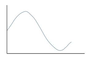
The analog-to-digital converters perform this type of function to create a series of digital values out of the given analog signal. The following figure represents an analog signal. This signal to get converted into digital, has to undergo sampling and quantizing.

The quantizing of an analog signal is done by discretizing the signal with a number of quantization levels. Quantization is representing the sampled values of the amplitude by a finite set of levels, which means converting a continuous-amplitude sample into a discrete-time signal.
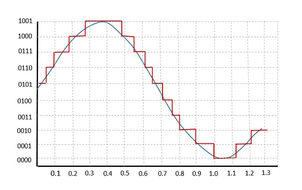
The following figure shows how an analog signal gets quantized. The blue line represents analog signal while the brown one represents the quantized signal.

Both sampling and quantization result in the loss of information. The quality of a Quantizer output depends upon the number of quantization levels used. The discrete amplitudes of the quantized output are called as representation levels or reconstruction levels. The spacing between the two adjacent representation levels is called a quantum or step-size.
The following figure shows the resultant quantized signal which is the digital form for the given analog signal.

This is also called as Stair-case waveform, in accordance with its shape.
There are two types of Quantization - Uniform Quantization and Non-uniform Quantization.
The type of quantization in which the quantization levels are uniformly spaced is termed as a Uniform Quantization. The type of quantization in which the quantization levels are unequal and mostly the relation between them is logarithmic, is termed as a Non-uniform Quantization.
There are two types of uniform quantization. They are Mid-Rise type and Mid-Tread type. The following figures represent the two types of uniform quantization.

Figure 1 shows the mid-rise type and figure 2 shows the mid-tread type of uniform quantization.
· The Mid-Rise type is so called because the origin lies in the middle of a raising part of the stair-case like graph. The quantization levels in this type are even in number.
· The Mid-tread type is so called because the origin lies in the middle of a tread of the stair-case like graph. The quantization levels in this type are odd in number.
· Both the mid-rise and mid-tread type of uniform quantizers are symmetric about the origin.
For any system, during its functioning, there is always a difference in the values of its input and output. The processing of the system results in an error, which is the difference of those values.
The difference between an input value and its quantized value is called a Quantization Error. A Quantizer is a logarithmic function that performs Quantization .An analog-to-digital converter (ADC) works as a quantizer.
The following figure illustrates an example for a quantization error, indicating the difference between the original signal and the quantized signal.

It is a type of quantization error, which usually occurs in analog audio signal, while quantizing it to digital. For example, in music, the signals keep changing continuously, where a regularity is not found in errors. Such errors create a wideband noise called as Quantization Noise.
The word Companding is a combination of Compressing and Expanding, which means that it does both. This is a non-linear technique used in PCM which compresses the data at the transmitter and expands the same data at the receiver. The effects of noise and crosstalk are reduced by using this technique.
There are two types of Companding techniques. They are −
· Uniform quantization is achieved at A = 1, where the characteristic curve is linear and no compression is done.
· A-law has mid-rise at the origin. Hence, it contains a non-zero value.
· A-law companding is used for PCM telephone systems.
· Uniform quantization is achieved at µ = 0, where the characteristic curve is linear and no compression is done.
· µ-law has mid-tread at the origin. Hence, it contains a zero value.
· µ-law companding is used for speech and music signals.
µ-law is used in North America and Japan.