Hydraulic Jump
OBJECTIVE
To study the characteristics of a hydraulic jump.
INTRODUCTION
A hydraulic jump occurs in the transition from supercritical to subcritical flow. The depths of flow upstream and downstream of the jump are called conjugate depths. The transition between supercritical and subcritical flow results with an effective energy loss that cannot be neglected. The hydraulic jump has many applications in open channel and drainage systems. The most common application is to provide energy dissipation in hydraulic structures such as dams and weirs in order to prevent downstream scouring. The hydraulic jump can also be used to maintain high water levels in channels for irrigation or other water distribution purposes. Knowledge of the surface profile of a hydraulic jump is desirable in this case for designing the freeboard for the channel. The hydraulic jump is also important in the design and analysis of storm sewer systems as the increase in downstream water depth may result with surcharged pipe flow condition.
THEORY
Consider the flow under a sluice gate in a horizontal channel such that a hydraulic jump occurs as shown in Figure (4.20). Between sections 1 and 2, the head loss is negligible and thus the corresponding specific energies become equivalent

APPARATUS
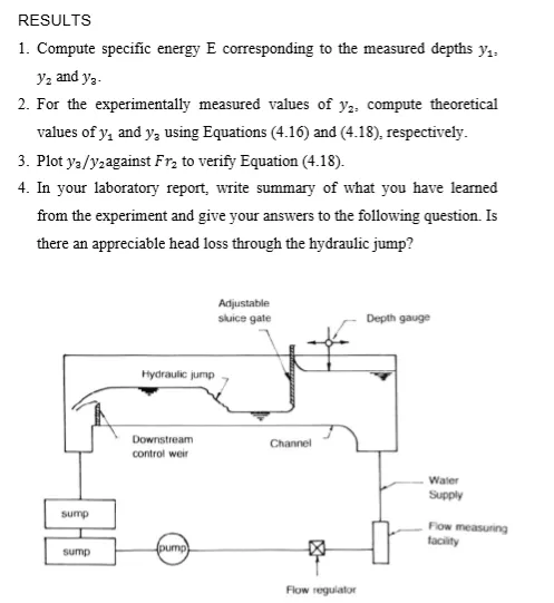
A schematic diagram of the apparatus is shown in Figure (4.21). The channel has a rectangular cross section and an adjustable weir control at the downstream location. Water is supplied constantly into the channel, and its rate can be varied by a flow regulator valve. An adjustable sluice gate is also available. The flow rate is determined using a flow measuring facility and the water depth by a measuring gauge.
PROCEDURE
1. Fix the sluice gate such that the flow under the gate will be supercritical.
2. Admit water supply to the channel and obtain the desired water depths by adjusting the flow control valve and varying the height of the downstream weir.
3. When the flow becomes steady, measure the flow rate and depths y1, y2 and y3.
4. Repeat the procedure for five different flow rates.