Steering Components (Automobile)
Steering Column
The steering column is primarily a supported shaft that connects the driver’s steering wheel to the gear unit. The steering column in the modern automobile is a complex mechanism. It is designed to collapse in a collision to protect the driver. In some installations it may be tilted and telescoped to place it at a convenient angle for the driver. It also contains steering gear and transmission locks. A panic stop through braking slows the vehicle at the maximum deceleration rate of 6 m / s and the required time to stop the vehicle from 32 kmph is 1.5 seconds. This panic stop tends to lift the passengers and driver from their seats and carry them into front of the compartment, unless they are secured with seat and shoulder belts. In a head-on collision, two collisions actually occur. The first is the vehicle’s collision with the object and the second is the occupants’ collision with the instrument panel and windshield in the front of the passenger compartment. The modern passenger car front end is designed to crush approximately 15.5 mm / km on collision, in order to decelerate the passenger compartment in the longest possible time period and, thereby reduce the severity of the secondary collision of the occupants. In a head-on collision, the driver is thrown against the steering wheel about one one-hundredth of a second after the front of the vehicle begins to crush. The old-style steering column is often pushed into the driver as the front of the vehicle is collapsed. Impact absorbing steering columns have been designed to collapse their lower section rather than pushed back. The upper end of these columns is also designed to absorb the secondary impact of the driver hitting the wheel by collapsing.
Construction.
The steering column must be strong and rigid enough to support normal driving loads and yet collapse at a controllable rate when collision loads are applied. The steering column consists of three major components, a steering shaft, a shift tube, and a column or mast jacket. The steering shaft connects the steering wheel to the steering gear unit through a universal joint type coupling. In some of the old steering gears, an extension of the steering gear worm shaft forms the steering shaft. A shift tube surrounds the steering shaft, the upper end of which is connected to the shift selector lever and the lower end has a bell crank that attaches to the shift linkages. The shift tube is enclosed in the mast jacket, which provides the support to shaft bearings, the mounting brackets, and column trim. The mast jacket is held in the vehicle by a floor plate retainer at the lower end and a break-away bracket just below the instrument panel. Suitable attachments are added to prevent any upward movement and to allow the column to move downward in a collision.
The earlier impact absorbing mast jackets have a section with diamond perforation cutouts which bulge outwards in a collision, allowing the jacket to shorten. The second generation impact absorbing mast jacket is made of two tubes. The upper tube just slips over the lower tube and steel balls in an injected plastic sleeve are wedged between the two tubes, making a secure mast jacket. The steel balls extrude grooves in the tubes as they are forced together during collision, and thus gradually slow the secondary driver’s impact at a controlled rate.
An adapter is used at each end of the mast jacket to serve as either a bearing or bearing support for the shift tube and steering shaft. The shift tube is made of two or three short pieces of tubing, one fitted inside the other, and rectangular and round holes are made in the tubes at the joints. These joints are then injected with plastic to hold them in position and in a collision the plastic inserts in the hole are sheared, allowing the shift tubes to telescope together. The shift tube in all steering columns provides rigidity, even though the vehicle may be equipped with a floor mounted gear shift lever.
The steering shaft has two sections. The upper section is a solid rod that fits into a hollow lower section. Two external flats on the upper section mate with internal flats in the lower section to transmit steering effort. Plastic inserts are injected into the holes in the lower section and around grooves in the upper section just under the holes, which lock the two steering shafts together. A collision shears the plastic due to which the steering shaft becomes telescope and shorter.
In addition to upper steering shaft bearing and steering wheel, there are number of items such as the transmission selector lever, turn signal switch, emergency flasher switch, ignition switch, shift and steering lock mechanism, speed control, steering wheel tilt mechanism, and a means to allow the wheel to travel in and out, which are installed on the upper end of the steering column depending upon the automobile model.
The transmission selector lever is connected to the shift tube, which has a gate that restricts shifter movement between neutral and drive unless the shift lever is shifted preventing accidental movement into a gear. The selector lever fits through a housing or hub, which trims the upper end of the steering column.
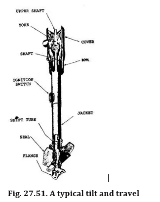
The turn signal switch is located directly under the steering wheel. After a turn is completed, a protrusion on the bottom of the steering wheel cancels the signal. When the horn is actuated, contact is made between the slip ring, placed on the steering wheel, and the steering coulumn which completes the horn circuit to ground and blows the horn. Tilting and telescope travelling steering columns have a much more complex upper steering column end (Fig. 27.51). The upper end of the steering shaft is fitted with a yoke, which forms the part of the universal joint. A short upper shaft is also fitted with a yoke. The universal joint is incorporated with a plastic sphere that fits between the two yokes. The yoke and upper shaft are enclosed in support housing and end cover. The upper shaft support swivels up and down in the housing, locking in a number of positions. The position locking shoes are released with a lever to tilt the steering wheel to a new position. The hollow upper shaft slides into the hollow upper yoke to allow the steering wheel to travel in and out. It is held in position with a cam-type wedge locking into a keyway in the yoke.
Service.
A normal steering column service involves work on the upper end of the steering column, Which can be done with the steering column remaining in the car. Any work on the steering column requires removal of steering wheel. The upper trim, often a horn button, bar or ring must be removed to separate steering wheel. Removal of upper trim exposes the steering wheel nut. The steering wheel requires pulling from a set of splines on the steering shaft, after the
nut is removed, for which, the pullers are used. Removal of steering wheel exposes the turn signal switch mechanism. The position of the master spline should be noted to reinstall the steering wheel. Repair work necessary on the parts can be carried out using proper tool and following applicable shop manual.
Steering Gears
The steering gearbox provides the driver with a leverage to enable him to exert a large force at the road wheel with a minimum effort, and to control the direction of the wheel. Turning effort on the steering wheel is multiplied through the steering gears to turn the front wheels, even when the vehicle is at rest. Therefore, the steering gearbox has two main functions. It produces a gear reduction between the input steering wheel and the output drop arm (Pitman arm) and it redirects the input to output axis of rotation through a right angle.
The overall angular gear ratio between the steering wheel and the road wheel varies from about 12:1 to 30:1, depending on the load on the road wheels and the type of steering. The lower ratio is for the light small vehicles and the higher ratio for heavy vehicles. As the ratio is lowered, a more number of turns are required to move the wheels from lock to lock making it difficult for a rapid change in vehicle direction.
Normally, the steering road wheel stub axles must be able to twist through a maximum steering angle of 40 degrees either side of straight ahead position. Therefore, lock to lock drop arm angular displacement amounts to 80 degrees and with a 12:1 and 30:1 gear reduction the number of turns of the steering wheel would be as follows:
Lock to lock steering = 80 x 12/360 = 2.66 revolutions the wheel turns for 12:1 reduction.
Lock to lock steering = 80 x 30/360 = 6.66 revolutions the wheel turns for 30:1 reduction.
These results show that the while the 12:1 reduction requires the steering wheel to be rotated through 1:33 turns from the straight ahead position, the 30:1 reduction requires 3.33 turns which is more than twice of the former angular displacement. Thus with the 12:1 gear reduction, the steering may be heavy but can be turned from the straight ahead position to full lock and back again relatively quickly. However the 30:1 reduction provides a light steering wheel but the vehicle is forced to corner much slower if the driver is able to complete the manoeuvre safely.
Over the years, several types of steering gearbox have been used, these include :
(i) Screw and nut.
(ii) Rack and pinion. (Hi) Cam and peg.
(iv) Worm and roller.
(v) Worm and sector.
(vi) Re-circulating ball.
Screw and Nut Steering Gear Mechanism
The screw and nut type mechanism is the basic form for all the other types of steering gear box mechanisms (Fig. 27.52). This mechanism increases both the force and movement ratios. A small input effort applied to the end of a perpendicular lever fixed
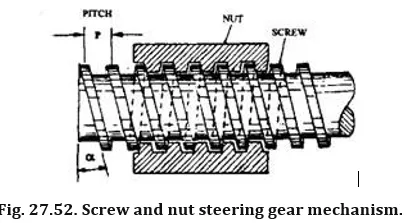
to the screw can move a much larger load axially along the screw, provided the nut is held against rotating.
If the screw is prevented from moving longitudinally, but revolves once within its nut, then the nut advances or retracts a distance equal to the axial length of one complete spiral groove loop. This distance is termed as the thread pitch or lead (p). The inclination of the spiral thread to the perpendicular of the screw axis is known as the helix angle (a). As the helix angle decreases the nut displaces greater load in an axial direction.
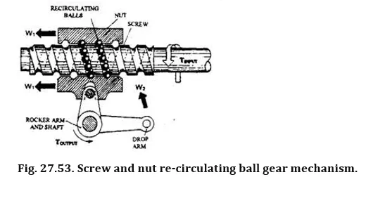
The engaged external and internal spiral threads of the screw and nut mechanism may be considered as a pair of infinitely long inclined planes. When the screw is rotated keeping the nut stationary, the inclined plane of the screw slides relative to that of the nut. Due to comparatively large surface areas in contact between the male and female threads and difficulty of maintaining an adequate supply of lubricant between the rubbing faces, this mechanism provides a relatively high friction, which causes low mechanical efficiency and high rate of wear. This friction can considerably be reduced by introducing a series of balls (Fig. 27.53) which roll between the inclined planes as the screw is rotated relatively to the nut.
The overall gear ratio in a screw and nut steering gearbox is achieved in two stages. In the first stage the nut moves along the pitch length for every one complete revolution of the steering wheel. In the second stage the linear movement of the nut is converted back to an angular one through an integral rocker lever and shaft.
The forward efficiency of a steering gearbox is denned as the ratio of the output work produced at the drop arm to move a given load to that of the input work performed at the steering wheel to achieve this movement,