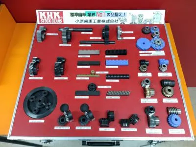
A sample box of various types of gears
Classification of Gears
What is a gear ?
A gear is a kind of machine element in which teeth are cut around cylindrical or cone shaped surfaces with equal spacing. By meshing a pair of these elements, they are used to transmit rotations and forces from the driving shaft to the driven shaft. Gears can be classified by shape as involute, cycloidal and trochoidal gears. Also, they can be classified by shaft positions as parallel shaft gears, intersecting shaft gears, and non-parallel and non-intersecting shaft gears. The history of gears is old and the use of gears already appears in ancient Greece in B.C. in the writing of Archimedes.
A sample box of various types of gears
Types of Gears
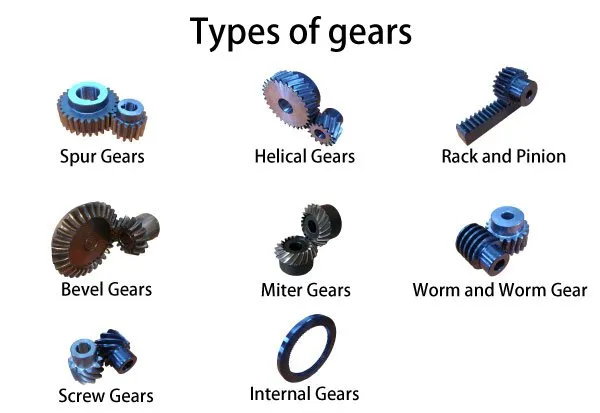
Various types of gears
There are many types of gears such as spur gears, helical gears, bevel gears, worm gears, gear rack, etc. These can be broadly classified by looking at the positions of axes such as parallel shafts, intersecting shafts and non-intersecting shafts.
It is necessary to accurately understand the differences among gear types to accomplish necessary force transmission in mechanical designs. Even after choosing the general type, it is important to consider factors such as: dimensions (module, number of teeth, helix angle, face width, etc.), standard of precision grade (ISO, AGMA, DIN), need for teeth grinding and/or heat treating, allowable torque and efficiency, etc.
Besides this page, we present more thorough gear technical information under Gear Knowledge (separate PDF page). In addition to the list below, each section such as worm gear, rack and pinion, bevel gear, etc. has its own additional explanation regarding the respective gear type. If it is difficult to view PDF, please consult these sections.
It is best to start with the general knowledge of the types of gears as shown below. But in addition to these, there are other types such as face gear, herringbone gear (double helical gear), crown gear, hypoid gear, etc.
Gears having cylindrical pitch surfaces are called cylindrical gears. Spur gears belong to the parallel shaft gear group and are cylindrical gears with a tooth line which is straight and parallel to the shaft. Spur gears are the most widely used gears that can achieve high accuracy with relatively easy production processes. They have the characteristic of having no load in the axial direction (thrust load). The larger of the meshing pair is called the gear and smaller is called the pinion.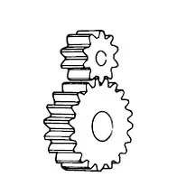
A sketch of spur gears

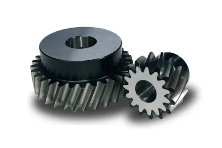
Helical gears are used with parallel shafts similar to spur gears and are cylindrical gears with winding tooth lines. They have better teeth meshing than spur gears and have superior quietness and can transmit higher loads, making them suitable for high speed applications. When using helical gears, they create thrust force in the axial direction, necessitating the use of thrust bearings. Helical gears come with right hand and left hand twist requiring opposite hand gears for a meshing pair.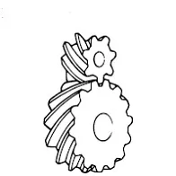
A sketch of helical gears
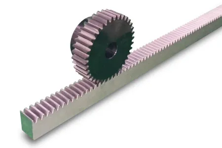
Same sized and shaped teeth cut at equal distances along a flat surface or a straight rod is called a gear rack. A gear rack is a cylindrical gear with the radius of the pitch cylinder being infinite. By meshing with a cylindrical gear pinion, it converts rotational motion into linear motion. Gear racks can be broadly divided into straight tooth racks and helical tooth racks, but both have straight tooth lines. By machining the ends of gear racks, it is possible to connect gear racks end to end.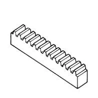
A sketch of gear rack
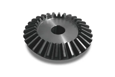
Bevel gears have a cone shaped appearance and are used to transmit force between two shafts which intersect at one point (intersecting shafts). A bevel gear has a cone as its pitch surface and its teeth are cut along the cone. Kinds of bevel gears include straight bevel gears, helical bevel gears, spiral bevel gears, miter gears, angular bevel gears, crown gears, zerol bevel gears and hypoid gears.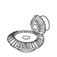
A sketch of bevel gears
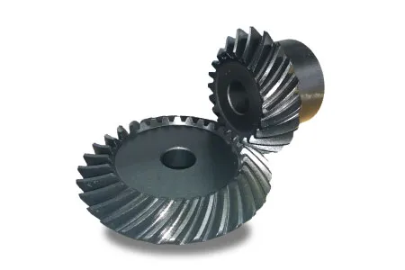
Spiral bevel gears are bevel gears with curved tooth lines. Due to higher tooth contact ratio, they are superior to straight bevel gears in efficiency, strength, vibration and noise. On the other hand, they are more difficult to produce. Also, because the teeth are curved, they cause thrust forces in the axial direction. Within the spiral bevel gears, the one with the zero twisting angle is called zerol bevel gear.
A sketch of spiral bevel gears
Screw gears are a pair of same hand helical gears with the twist angle of 45° on non-parallel, non-intersecting shafts. Because the tooth contact is a point, their load carrying capacity is low and they are not suitable for large power transmission. Since power is transmitted by the sliding of the tooth surfaces, it is necessary to pay attention to lubrication when using screw gears. There are no restrictions as far as the combinations of number of teeth.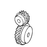
A sketch of screw gears

Miter gears are bevel gears with a speed ratio of 1. They are used to change the direction of power transmission without changing speed. There are straight miter and spiral miter gears. When using the spiral miter gears it becomes necessary to consider using thrust bearings since they produce thrust force in the axial direction. Besides the usual miter gears with 90° shaft angles, miter gears with any other shaft angles are called angular miter gears.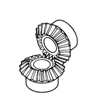
A sketch of miter gears

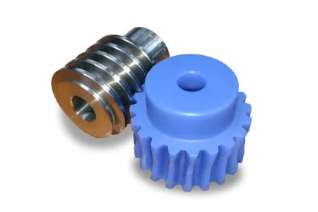
A screw shape cut on a shaft is the worm, the mating gear is the worm wheel, and together on non-intersecting shafts is called a worm gear. Worms and worm wheels are not limited to cylindrical shapes. There is the hour-glass type which can increase the contact ratio, but production becomes more difficult. Due to the sliding contact of the gear surfaces, it is necessary to reduce friction. For this reason, generally a hard material is used for the worm, and a soft material is used for worm wheel. Even though the efficiency is low due to the sliding contact, the rotation is smooth and quiet. When the lead angle of the worm is small, it creates a self-locking feature.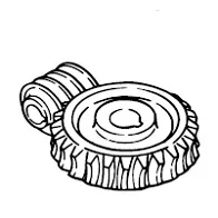
A sketch of worm gears
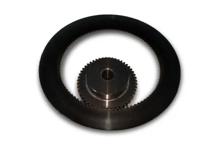
Internal gears have teeth cut on the inside of cylinders or cones and are paired with external gears. The main use of internal gears are for planetary gear drives and gear type shaft couplings. There are limitations in the number of teeth differences between internal and external gears due to involute interference, trochoid interference and trimming problems. The rotational directions of the internal and external gears in mesh are the same while they are opposite when two external gears are in mesh.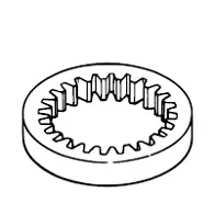
A sketch of internal gear

An overview of gears
(Important Gear Terminology and Gear Nomenclature in this picture)
![]() Worm
Worm
![]() Worm wheel
Worm wheel
![]() Internal gear
Internal gear
![]() Gear coupling
Gear coupling
![]() Screw gear
Screw gear
![]() Involute spline shafts and bushings
Involute spline shafts and bushings
![]() Miter gear
Miter gear
![]() Spur gear
Spur gear
![]() Helical gear
Helical gear
![]() Ratchet
Ratchet
![]() Pawl
Pawl
![]() Rack
Rack
![]() Pinion
Pinion
![]() Straight bevel gear
Straight bevel gear
![]() Spiral bevel gear
Spiral bevel gear