SLIDER CRANK MECHANISM ANALYSIS BY RELATIVE VELOCITY METHOD
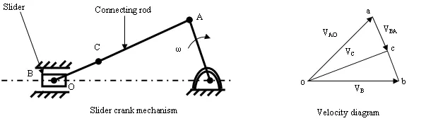
Angular velocity of link OA is given ω and velocity of point A can be given by, Va = ω×OA = VAO in the clockwise direction about O. Vais perpendicular to OA. So we know the direction and magnitude of Va. The velocity of slider B is along OB. The configuration and velocity diagram for this problem is given below.
Fig. 3.5
Step 1. Take any point o and draw vector oa such that oa= ω × OA=VAO, perpendicular to OA in some suitable scale as shown in the velocity diagram.
Step 2. The velocity of point B with respect to A (VBA) is perpendicular to AB. From a draw a vector ab perpendicular to the line AB.
Step 3. The velocity of slider B is along the line of stroke OB, from o draw a line parallel to OB which will intersect vector ab at b. The vector obrepresent the velocity of slider B (VB).
The velocity of any point C on the connecting rod can be determined by the help of relation:
\[\frac{{{\mathbf{ac}}}}{{{\mathbf{ab}}}} = \frac{{{\text{AC}}}}{{{\text{AB}}}}{\text{ or }}{\mathbf{ac}} = {\mathbf{ab}} \times \frac{{{\text{AC}}}}{{{\text{AB}}}}\]
The point c can be located on the velocity diagram. Join o with c. vector oc represents the absolute velocity of point C with respect to O.
Example 3.1 In the mechanism as shown below, the crank O2A rotates at 600 r.p.m. in the anticlockwise direction. The length of link O2A= 12 cm and of link O1B= 60 cm. Find
a. Angular velocity of link O1A.
b. Velocity of slider at B.
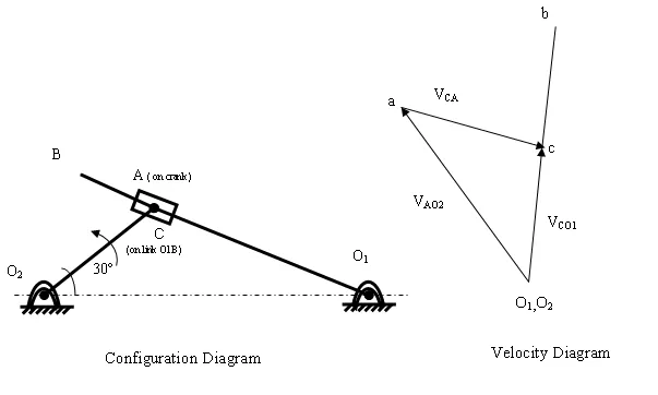
Fig. 3.6
Solution:
Given: N=600 r.p.m
\[\omega={\text{ }}\frac{{{\text{2}}\pi{\text{N}}}}{{{\text{6}}0}} = \frac{{{\text{2}}\pi\times {\text{6}}00}}{{{\text{6}}0}} = {\text{2}}0{\text{ }}\pi {\text{ rad}}/{\text{sec}}\]
The velocity of A with respect to O2
\[{{\text{V}}_{{\text{AO2}}}}= \omega\times{{\text{O}}_{\text{2}}}{\text{A}}={\text{2}}0\pi\times \frac{{{\text{12}}}}{{{\text{1}}00}} = {\text{7}}.{\text{53 m}}/{\text{s}}\]
In the configuration diagram let us take a point C on the link O1B. The velocity diagram can be drawn as explain below.
Step 1. O1 and O2 are fixed points on the configuration diagram so they are taken as single point (o1,o2) on the velocity diagram. The velocity of point A with respect to O2, VAO2 = 7.53 m/s is drawn as vector o2a in some suitable scale perpendicular to O2A.
Step 2. The velocity of point C with respect to A, VCA along the path of slider, O1B. From a draw a vector ac representing VCA along O1A. This will contain point c.
Step 3. The velocity of point C with respect to O1 is VCO1 and it will be perpendicular to O1A.Then from o1 draw a vector o1c representing VCO1this will intersect ac at point c.
Step 4. Locate the point b corresponding to point B such that
\[\frac{{{{\mathbf{o}}_{\mathbf{1}}}{\mathbf{b}}}}{{{{\mathbf{o}}_{\mathbf{1}}}{\mathbf{c}}}} =\frac{{{{\text{O}}_{\text{1}}}{\text{B}}}}{{{{\text{O}}_{\text{1}}}{\text{C}}}}\]
o1b= 5.55 m/s by measurement
o1b=VBO1
Angular velocity of link O1A
\[{\omega_{{\text{O1A}}}}={\omega _{{\text{O1B}}}}=\frac{{{{\text{V}}_{{\text{BO1}}}}}}{{{{\text{O}}_{\text{1}}}{\text{B}}}}= \frac{{{\text{5}}.{\text{55}}}}{{0.{\text{6}}0}}\]
= 9.25 rad/sec
(anticlockwise direction)