
Planar Mechanism
• The planar mechanism is the most common type of mechanism. The trajectory of one point on the planar mechanism lies on a plane during motion. The trajectory of all points on the planar mechanism lie on planes which are parallel to each other.
• For example, a door is a simple planar mechanism that consists of a moving link and a ground link. This mechanism can be described on a plane.
In a spatial mechanism, the motion of the links is not planar. For example, the trajectories of the links in a spherical mechanism form concentric spheres
Joints in a Planar Mechanism
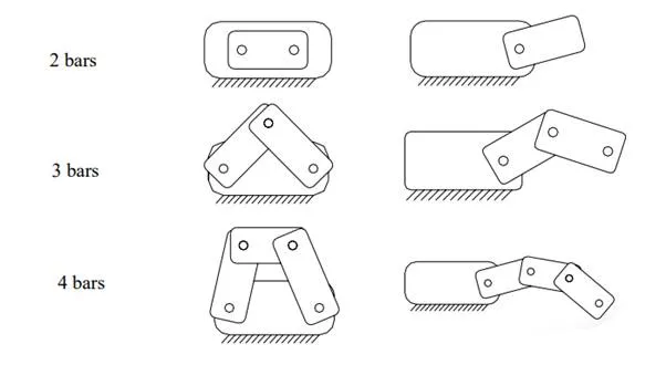
Links are connected by joints. There are 3 types of joints:
• Revolute joint permits rotational motion with respect to a fixed axis.
• Prismatic joint permits translational motion between of a pair of links.
• Direct contact joint permits both rotation and slide between links.
Both revolute joint and prismatic joint are single-DOF joints. Only one parameter is needed to describe the relative position between two links. The direct contact joint is a 2-DOF joint.
Joints in a Spatial Mechanism
• Helical joint is a one-DOF joint consists of a screw nut and a bolt.
• Cylindrical joint consists of a shaft and a sleeve, and permits two-DOF motion.
• A universal joint is a spherical joint which provides three-DOF motion.
• The direct contact joint in a spatial mechanism can have 5 DOF (point contact), 4 DOF (line contact) or 3 DOF (surface contact).
Linkage Design (I)
• The function of a mechanism in a machine is to convert the input force or to convert the input force or motion into desired output. motion into desired output.
• In a linearly proportional mechanism, the output motion or force is linearly proportional to the input.
• In some mechanisms, the relation between output and input is nonlinear. The number, type and connectivity of joints, and the length of links determine the characteristic of the mechanism. Such mechanism is called a linkage.
• The purpose of linkage design is The purpose of linkage design is to decide the length of the lin to decide the length of the links, the position ks, the position and type of the joints, and how to and type of the joints, and how to assemble the links so that th assemble the links so that the desired motion e desired motion can be achieved. can be achieved.
Linkage Design (II)
When analyzing a linkage, we often use a “skeleton diagram” to represent the type of joints, distances between joints, and which joints connect which links in the linkage
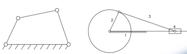
Linkage Design (III)
• The close-loop four-bar linkage has only 1 DOF, i.e., . only one actuator is needed to drive the linkage. It is the most popular and well-studied linkage.