
Examples Of Mechanisms; Terminology
The punch mechanism shown in Figure is a schematic representation of a device to punch holes in a workpiece when the oscillating crank through the coupler moves the punch up and down. The function of this mechanism is to transform a small force/torque applied to the crank into a large punching force. The specific shape of the crank, the coupler, and the punch does not affect this function. This function depends only on locations of points O, A, and B. If this is the case, then the lines connecting these points can represent this mechanism. Such a representation, shown in Figure, is called a skeleton representation of the mechanism. The power is supplied to crank 2, while punch 4 is performing the needed function.
In Figure , the lines connecting points O, A, and B are called links and they are connected to each other by joints. Links are assumed to be rigid. Revolute joints connect link 2 to link 3 and to the frame (at point O). A revolute joint is a pin, and it allows rotation in a plane of one link with respect to another. A revolute joint also connects the two links 3 and 4. Link 4 is allowed to slide with respect to the frame, and this connection between the frame and the link is called a prismatic joint. The motion is transferred from link 2, which is called the input link, to link 4, which is called the output link. Sometimes the input link is called a driver, and the output link the follower. Another example of a mechanism is the windshield wiper mechanism shown in Figure. The motion is transferred from the crank driven by a motor through the
A windshield wiper mechanism.
coupler to the left rocker. The two rockers, left and right, are connected by the rocker coupler, which synchronizes their motion. The mechanism comprising links 1 (frame), 2 (crank), 3 (coupler), and 4 (rocker) is called a four-bar mechanism. In this example, revolute joints connect all links. A kinematic chain is an interconnected system of links in which not a single link is fixed. Such a chain becomes a mechanism when one of the links in the chain is fixed. The fixed link is called a frame or, sometimes, a base link. In Figure 1.3 link 1 is a frame. A planar mechanism is one in which all points move in parallel planes.
A joint between two links restricts the relative motion between these links, thus imposing a constraining condition on the mechanism motion. The type of constraining condition determines the number of degrees of freedom (DOF) a mechanism has. If the constraining condition allows only one DOF between the two links, the corresponding joint is called a lower-pair joint. The examples are a revolute joint between links 2 and 3 and a prismatic joint between links 4 and 1 in Figure. If the constraint allows two DOF between the two links, the corresponding joint is called a high-pair joint. An example of a high-pair joint is a connection between the cam and the roller in Figure 1.1, if, in addition to rolling, sliding between the two links takes place.
A dump truck mechanism is shown in Figure 1.5, and its skeleton diagram in Figure 1.6. This is an example of a compound mechanism comprising two simple ones: the first, links 1–2–3, is called the slider-crank mechanism and the second, links 1–3–5–6, is called the four-bar linkage. The two mechanisms work in sequence (or they are functionally in series): the input is the displacement of the piston in the hydraulic cylinder, and the output is the tipping of the dump bed.
All the previous examples involved only links with two connections to other links. Such links are called binary links. In the example of Figure 1.6, in addition to binary links, there is link 2, which is connected to three links: 1 (frame), 3, and 5. Such a link is called a ternary link. It is possible to have links with more than three connections
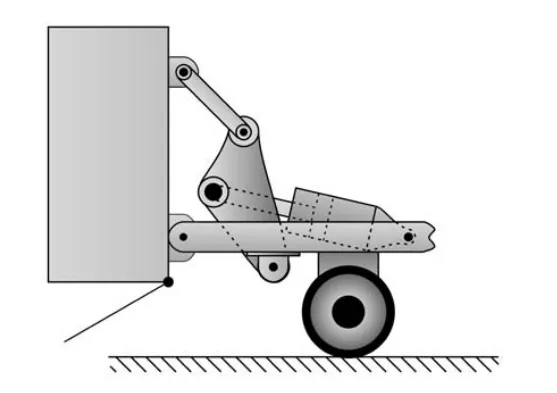
Dump truck mechanism.
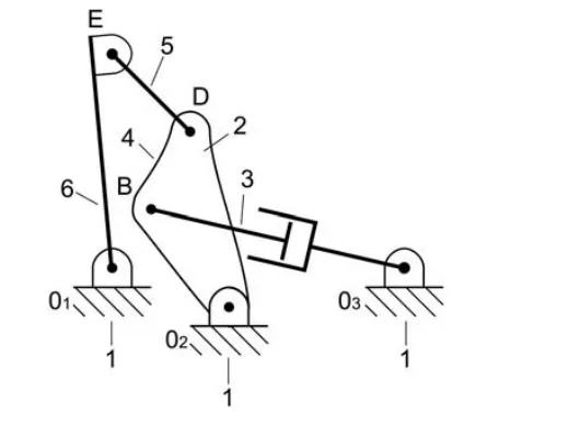
Skeleton of the dump truck mechanism.