Motor driven systems usually have optimal motor speeds at which the motor operates with the greatest power and efficiency. These motor speeds are expressed in rotations per minute (RPM) of the motor shaft.
In many applications, this optimal motor speed is not the speed (RPM) at which the load is required to be driven. For such cases, gear trains are used. Gear trains are two or more gears intermeshed together. These gears are attached to the motor shaft and load shaft, and are coupled together through inter-meshed teeth. Gear ratio, is a direct measure of the ratio of load shaft rotational speed to motor shaft rotational speed.
Let us walk you through the method we use to determine gear ratios for a gear train.
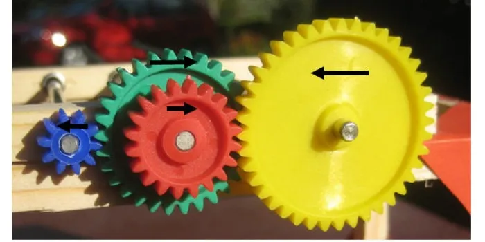
Step 1. Determine the number of gears in the gear train.
A drive gear is the one attached to the motor shaft. A driven gear is the one attached to the load shaft. There may be any number of gears successively connected to transmit power from the drive gear to the driven gear. These are called idler gears. They are used to share the work of generating the desired gear ratio when direct gearing between the drive gear and the driven gear is difficult as those gears are unwieldy or not readily available.
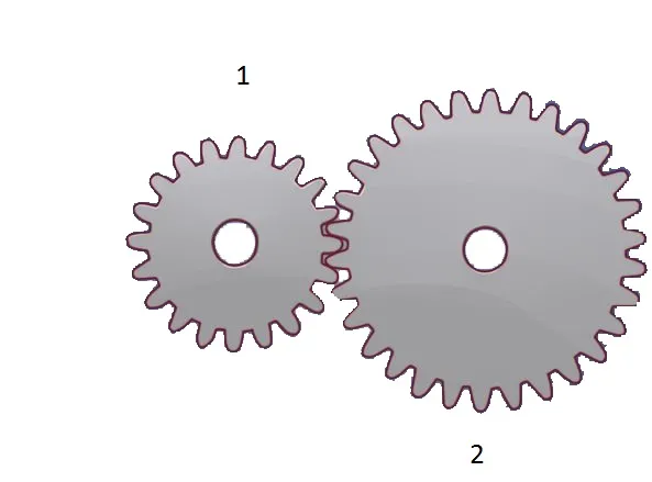
Step 2. Note the number of teeth on each gear used in the system.
Gear ratio is determined starting with the drive gear, so it should be noted which gear in the gear train, counting from the drive gear to the driven gear, has what number of teeth.
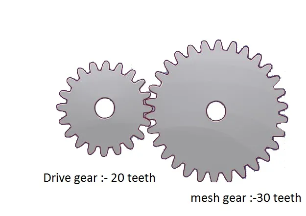 step 3. Calculate the gear ratio for the drive gear and the first gear to which it meshes.
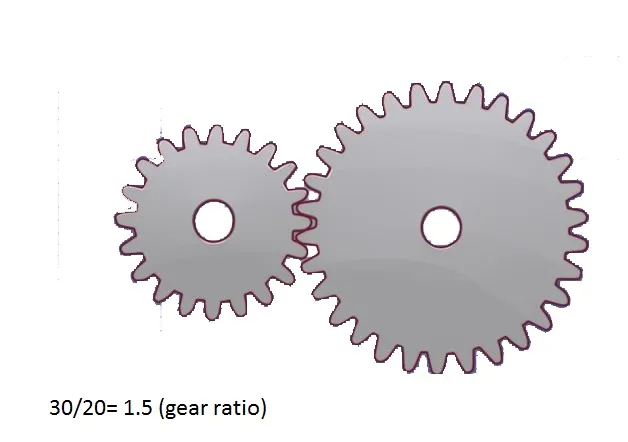
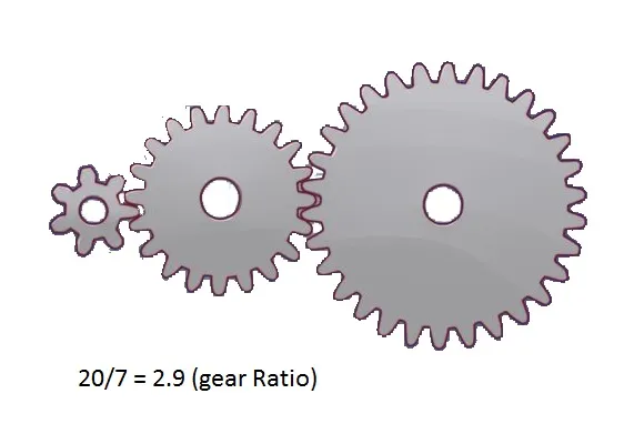
The gear ratio is simply the number of teeth on the meshed gear divided by the number of teeth on the drive gear with which it meshes.
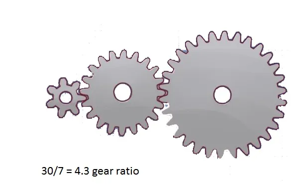
Step 4. Determine the gear ratio for the next gear in the gear train. If there is only 1 driver gear and 1 load gear, the calculation is complete. If there are idler gears in the gear train, proceed with the calculation. Divide the number of teeth on the meshed gear by the number of teeth on the gear with which it meshes.
Step 5. Determine the intermediate gear ratios. Figure for each idler gear in the system, starting from the drive gear and working toward the load gear. Treat the preceding gear, which could be the drive gear or the preceding idler gear in the train, as if it were the drive gear as far as this next gear is concerned. Divide the number of teeth on the meshed gear by the number of teeth on the gear it meshes with to calculate the intermediate gear ratios.
step 6. Finish the overall gear ratio calculation. When you have each pair of gear ratios determined, there should be 1 less ratio than the number of gears in the train. Multiply all of these ratios together. The result is the overall gear ratio.

so the over all gear ratio is calculated by this method.