
The Loop-Closure Equation
Our discussion of the position-difference and apparent-position vectors has been quite abstract so far, the intent being to develop a rigorous foundation for the analysis of motion in mechanical systems. Certainly, precision is not without merit, because it this rigor !hat permits science to predict a correct result in spite of the personal prejudices and emotions of the analyst. However, tedious developments are not interesting unless they lead to applications in problems of real life. Although there are yet many fundamental principles to be discovered, it might be well at this point to show the relationship between the relative position vectors discussed above and some of the typical linkages met in real machines.
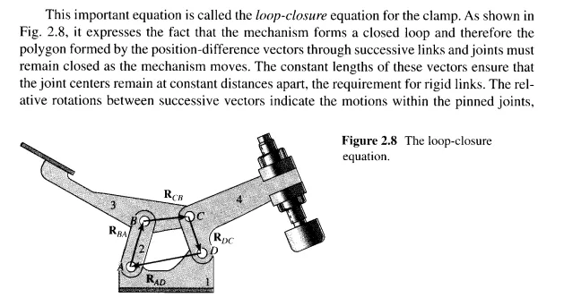
One of the most common and most useful of all mechanisms is the four-bar linkage. One example is the clamping device shown in Fig. 2.6. A brief study of the assembly drawing shows that, as the handle of the clamp is lifted, the clamping bar swings away from the clamping surface, thereby opening the clamp. As the handle is pressed, the clamping bar swings down and the clamp closes again. If we wish to design such a clamp accurately, however, things are not quite so simple. It may be desirable, for example, for the clamp to open at a given rate for a certain rate of lift of the handle. Such relationships are not obvious; they depend on the exact dimensions of the various parts and the relationships or
interactions between the parts. To discover these relationships, a rigorous description of the essential features of the device is required. The position-difference and apparent-position vectors can be used to provide such a description.
Figure 2.7 shows the detail drawings of the individual links of the disassembled clamp. Although not shown, the detail drawings would be completely dimensioned, thus fixing once and for all the complete geometry of each link. The assumption that each is a rigid link ensures that the position of any point on anyone of the links can be determined precisely relative to any other point on the same link by simply identifying the proper points and scaling the appropriate detail drawing.
The features that are lost in the detail drawings, however, are the interrelationships between the individual parts-that is, the constraints which ensure that each link will move relative to its neighbours in the prescribed fashion. These constraints are, of course, provided by the four pinned joints. Anticipating that they will be of importance in any description of the linkage, we label these pin centres A, B, C, and D and we identify the appropriate points on link 1 as A I and Dl, those on link 2 as A2 and B2, and so on. As shown in Fig. 2.7, we also pick a different coordinate system rigidly attached to each link.
Because it is necessary to relate the relative positions of the successive joint centres, we define the position difference vectors RAD on link 1, RBA on link 2, RCB on link 3, and RDc on link 4. We note again that each of these vectors appears constant to an observer fixed in the coordinate system of that particular link; the magnitudes of these vectors are obtainable from the constant dimensions of the links.
A vector equation can also be written to describe the constraints provided by each of the revolute (pinned) joints. Notice that no matter which position or which observer is chosen, the two points describing each pin centre-for example, A 1 and A2-remain
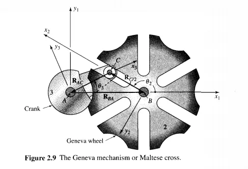
entire cycle of motion. Once the roller leaves the slot, the motion is controlled by the two mating circular arcs on links 2 and 3. A new form of the loop-closure equation is required for this part of the cycle.
Mechanisms can, of course, be connected together forming a multiple-loop kinematic chain. In such a case more than one loop-closure equation is required to model the system completely. The procedures for obtaining the equations, however, are identical to 1/1ose illustrated in the above examples.