Kinematic Inversion
In Section 1.4 we noted that every mechanism has a fixed link called the frame. Until a frame link has been chosen, a connected set of links is called a kinematic chain. When different links are chosen as the frame for a given kinematic chain, the relative motions between the various links are not altered, but their absolute motions (those measured with respect to the frame link) may be changed drastically. The process of choosing different links of a chain for the frame is known as kinematic inversion.
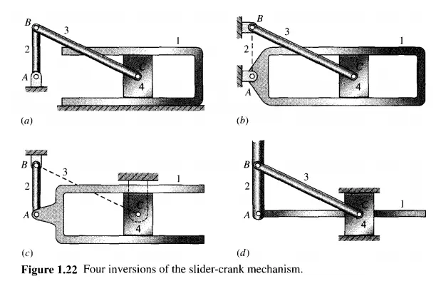
In an n-link kinematic chain, choosing each link in turn as the frame yields n distinct kinematic inversions of the chain, n different mechanisms. As an example, the four-link slider-crank chain of Fig. 1.22 has four different inversions.
Figure 1.22a shows the basic slider-crank mechanism, as found in most internal combustion engines today. Link 4, the piston, is driven by the expanding gases and forms the input; link 2, the crank, is the driven output. The frame is the cylinder block, link 1. By reversing the roles of the input and output, this same mechanism can be used as a compressor.
Figure 1.22b shows the same kinematic chain; however, it is now inverted and link 2 is stationary. Link 1, formerly the frame, now rotates about the revolute at A. This inversion of the slider-crank mechanism was used as the basis of the rotary engine found in early aircraft.
Another inversion of the same slider-crank chain is shown in Fig. 1.22c; it has link 3, formerly the connecting rod, as the frame link. This mechanism was used to drive the wheels of early steam locomotives, link 2 being a wheel.
The fourth and final inversion of the slider-crank chain has the piston, link 4, stationary. Although it is not found in engines, by rotating the figure 90° clockwise this mechanism
can be recognized as part of a garden water pump. It will be noted in the figure tha\ the prismatic pair connecting links I and 4 is also inverted; that is, the "inside" and "outside" elements of the pair have been reversed.
Grashof's Law
A very important consideration when designing a mechanism to be driven by a motor, obviously, is to ensure that the input crank can make a complete revolution. Mechanisms in which no link makes a complete revolution would not be useful in such applications. For the four-bar linkage, there is a very simple test of whether this is the case.
Grashof's law states that for a planar four-bar linkage, the sum of the shortest and longest link lengths cannot be greater than the sum of the remaining two link lengths if there is to be continuous relative rotation between two members. This is illustrated in Fig. 1.23, where the longest link has length I,the shortest link has length s, and the other two links have lengths p and q. In this notation, Grashof's law states that one of the links, in particular the shortest link, will rotate continuously relative to the other three links if and only if

If this inequality is not satisfied, no link will make a complete revolution relative to another.
Attention is called to the fact that nothing in Grashof's law specifies the order in which the links are connected, or which link of the four-bar chain is fixed. We are free, therefore, to fix any of the four links. When we do so, we create the four inversions of the four-par linkage shown in Fig. 1.23. All of these fit Grashof's law, and in each the link s makes a complete revolution relative to the other links. The different inversions are distinguished by the location of the link s relative to the fixed link.
If the shortest link s is adjacent to the fixed link, as shown in Figs. 1.23a and 1.23b, we obtain what is called a crank-rocker linkage. Link s is, of course, the crank because it is able to rotate continuously; and link p, which can only oscillate between limits, is the rocker.
The drag-link mechanism, also called the double-crank linkage, is obtained by fixing the shortest link s as the frame. In this inversion, shown in Fig. 1.23c, both links adjacent to scan rotate continuously, and both are properly described as cranks; the shorter of the two is generally used as the input.
Although this is a very common mechanism, you will find it an interesting challenge to devise a practical working model that can operate through the full cycle.
By fixing the link opposite to s we obtain the fourth inversion, the double-rocker mechanism of Fig. 1.23d. Note that although link s is able to make a complete revolution, neither link adjacent to the frame can do so; both must oscillate between limits and are therefore rockers.
In each of these inversions, the shortest link s is adjacent to the longest link I. However, exactly the same types of linkage inversions will occur if the longest link I is opposite the shortest link s; you should demonstrate this to your own satisfaction. Rouleaux’s approaches the problem somewhat differently but, of course, obtains the same results. In this approach, and using Fig. 1.23a, the links are named
where I need not be the longest link. Then the following conditions apply:
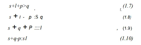
These four conditions are illustrated in Fig. 1.24 by showing what happens if the conditions are not met.