Inertia Forces and D’Alembert’s Principle
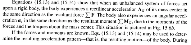
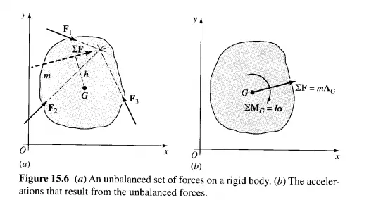
engineering design, however, the desired motions of the machine members are often specified in advance by other machine requirements. The problem then is: Given the motion of the machine elements, what forces are required to produce these motions? The problem requires (I) a kinematic analysis in order to determine the translational and rotational accelerations of the various members and (2) definitions of the actual shapes, dimensions, and material specifications, in order to determine the centroids and mass moments of inertia of the members. In the examples to be discussed here, only the results of the kinematic analysis will be presented; methods of finding these were presented in Chapter 4. The selection of the materials, shapes, and many of the dimensions of machine members form the subject of machine design and is also not further discussed here. Because, in the dynamic analysis of machines, the acceleration vectors are usually known, an alternative form of Eqs. (15.13) and (15.14) is often convenient in determining the forces required to produce these known accelerations. Thus, we can write
where it is understood that both the external and the inertia forces and torques are to be included in the summations. Equations (15.17) are useful because they permit us to take the summation of moments about any axis perpendicular to the plane of motion.
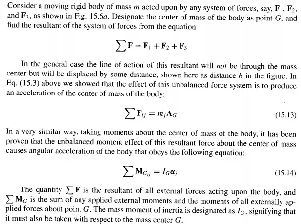
D' Alembert's principle is summarized as follows: The vector sum of all external forces and inertia forces acting upon a system of rigid bodies is zero. The vector sum of all external moments and inertia torques acting upon a system of rigid bodies is also separately zero. When a graphical solution by a force polygon is desired, Eqs. (15.17) can be combined. In Fig. 15.7a, a rigid link 3 is acted upon by the external forces F23 and F43. The resultant F 23 + F 43 produces an acceleration AG of the center of mass, and an angular