Classification Of Mechanisms
An ideal system of classification of mechanisms would be one that allows the designer to enter the system with a set of specifications and leave with one or more mechanisms that satisfy those specifications. Though history’s shows that many attempts have been made, none have been very successful in devising a completely satisfactory method. In view of the fact that the purpose of a mechanism is the transformation of motion, we shall follow Torfason's lead6 and classify mechanisms according to the type of motion transformation. Altogether, Torfason displays 262 mechanisms, each of which is capable of variation in dimensions. His categories are as follows:
Snap-Action Mechanisms The mechanisms of Fig. 1.7 are typical of snap-action mechanisms, but Torfason also includes spring clips and circuit breakers.
Linear Actuators Linear actuators include:
1. Stationary screws with traveling nuts.
2. Stationary nuts with traveling screws.
3. Single- and double-acting hydraulic and pneumatic cylinders.
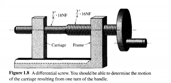
Fine Adjustments Fine adjustments may be obtained with screws, including the differential screw of Fig. 1.8, worm gearing, wedges, levers and levers in series, and various motion-adjusting mechanisms.
Clamping Mechanisms Typical clamping mechanisms are the C-clamp, the woodworker's screw clamp, cam- and lever-actuated clamps, vises, presses such as the toggle press of Fig. 1.7b, collets, and stamp mills.
Locational Devices Torfason pictures 15 locational mechanisms. These are usually self-centering and locate either axially or angularly using springs and detents.
Ratchets and Escapements There are many different forms of ratchets and escapements, some quite clever. They are used in locks, jacks, clockwork, and other applications requiring some form of intermittent motion. Figure 1.9 illustrates four typical applications.
The ratchet in Fig. 1.9a allows only one direction of rotation of wheel 2. Pawl 3 is held against the wheel by gravity or a spring. A similar arrangement is used for lifting jacks, which then employ a toothed rack for rectilinear motion.
Figure 1.9h is an escapement used for rotary adjustments.
Graham's escapement of Fig. 1.9c is used to regulate the movement of clockwork. Anchor 3 drives a pendulum whose oscillating motion is caused by the two clicks engaging the escapement wheel 2. One is a push click, the other a pull click. The lifting and engaging of each click caused by oscillation of the pendulum results in a wheel motion which, at the same time, presses each respective click and adds a gentle force to the motion of the pendulum.
The escapement of Fig. 1.9d has a control wheel 2 which may rotate continuously to allow wheel 3 to be driven (by another source) in either direction.
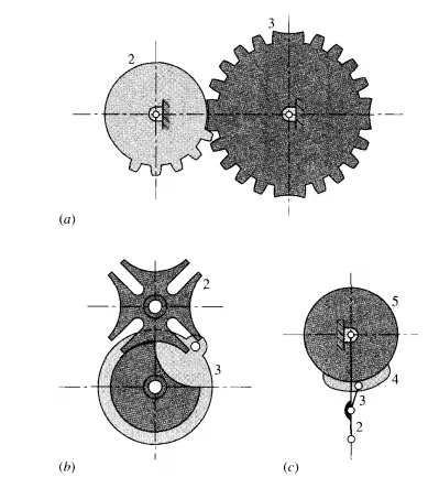
Indexing Mechanisms
The indexer of Fig. 1.l0a uses standard gear teeth; for light loads, pins can be used in wheel 2 with corresponding slots in wheel 3, but neither form should be used if the shaft inertias are large.
Figure 1.1Ob illustrates a Geneva-wheel indexer. Three or more slots (up to 16) may be used in driver 2, and wheel 3 can be geared to the output to be indexed. High speeds and large inertias may cause problems with this indexer.
The toothless ratchet 5 in Fig. 1.IOc is driven by the oscillating crank 2 of variable throw. Note the similarity of this to the ratchet of Fig. 1.9a.
Torfason lists nine different indexing mechanisms, and many variations are possible.
Swinging or Rocking Mechanisms
The class of swinging or rocking mechanisms is often termed oscillators; in each case the output member rocks or swings through an angle that is generally less than 3600 • However, the output shaft can be geared to a second shaft to produce larger angles of oscillation.
Figure l.lla is a mechanism consisting of a rotating crank 2 and a coupler 3 containing a toothed rack that meshes with output gear 4 to produce the oscillating motion.
In Fig. 1.11b, crank 2 drives member 3, which slides on output link 4, producing a rocking motion. This mechanism is described as a quick-return linkage because crank 2 rotates through a larger angle on the forward stroke of link 4 than on the return stroke.
Figure I. I Ic is a four-har linkage called the crank-and-rocker mechanism. Crank 2 drives rocker 4 through coupler 3. Of course, link I is the frame. The characteristics of the rocking motion depend on the dimensions of the links and the placement of the frame points.
Figure I. lId illustrates a cam-and-follower mechanism, in which the rotating cam 2 drives link 3, called the follower, in a rocking motion. There are an endless variety of cam-andfollower mechanisms, many of which will be discussed in Chapter 5. In each case the cams can be formed to produce rocking motions with nearly any set of desired characteristics.
Reciprocating Mechanisms
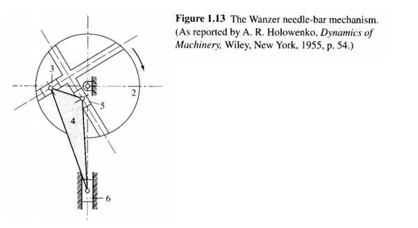
Repeating straight-line motion is commonly obtained using pneumatic and hydraulic cylinders, a stationary screw and traveling nut, rectilinear drives using reversible motors or reversing gears, as well as cam-and-follower mechanisms. A variety of typical linkages for obtaining reciprocating motion are shown in Figs. 1.12 and 1.I3.
The offset slider-crank mechanism shown in Fig. 1.12a has velocity characteristics that differ from an on-centre slider crank (not shown). If connecting rod 3 of an on-center slider-crank mechanism is large relative to the length of crank 2, then the resulting motion is nearly harmonic.
Link 4 of the Scotch yoke mechanism shown in Fig. 1.I2h delivers exact harmonic motion.
The six-bar linkage shown in Fig. 1.12c is often called the shaper mechanism, after the name of the machine tool in which it is used. Note that it is derived from Fig. I. I2h by adding coupler 5 and slider 6. The slider stroke has a quick-return characteristic.
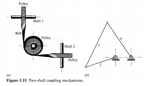
Figure 1.12d shows another version of the shaper mechanism, which is often termed the Whitworth quick-return mechanism. The linkage is shown in an upside-down configuration to show its similarity to Fig. 1.12c.
In many applications, mechanisms are used to perform repetitive operations such as pushing parts along an assembly line, clamping parts together while they are welded, or folding cardboard boxes in an automated packaging machine. In such applications it is often desirable to use a constant-speed motor; this will lead us to a discussion of Grashof's law in Section 1.9. In addition, however, we should also give some consideration to the power and timing requirements.
In these repetitive operations there is usually a part of the cycle when the mechanism is under load, called the advance or working stroke, and a part of the cycle, called the return stroke, when the mechanism is not working but simply returning so that it may repeat the operation. In the offset slider-crank mechanism of Fig. 1.12a, for example, work may be required to overcome the load F while the piston moves to the right from C, to Cz but
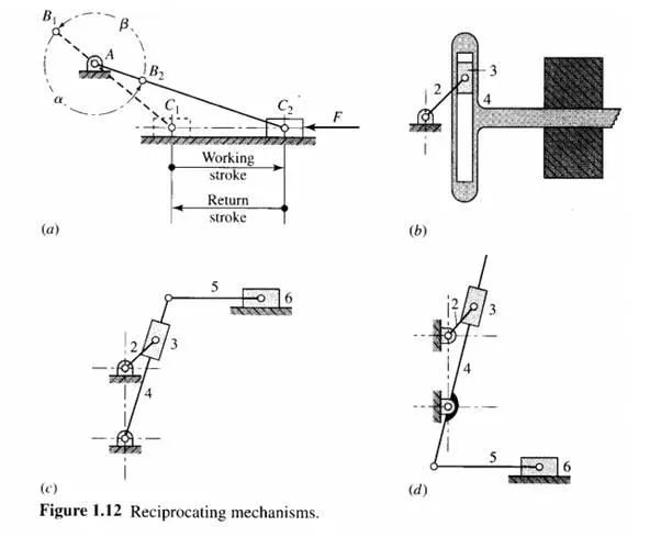
not during its return to position C1 because the load may have been removed. In such situations, in order to keep the power requirements of the motor to a minimum and to avoid wasting valuable time, it is desirable to design the mechanism so that the piston will move much faster through the return stroke than it does during the working stroke-that is, to use a higher fraction of the cycle time for doing work than for returning.
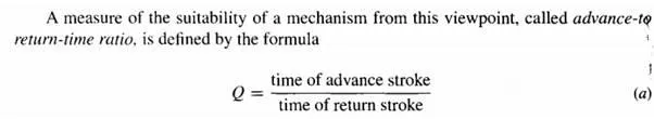
A mechanism for which the value of Q is high is more desirable for such repetitive operations than one in which Q is lower. Certainly, any such operations would use a mechanism for which Q is greater than unity. Because of this, mechanisms with Q greater than unity are called quick-return mechanisms.
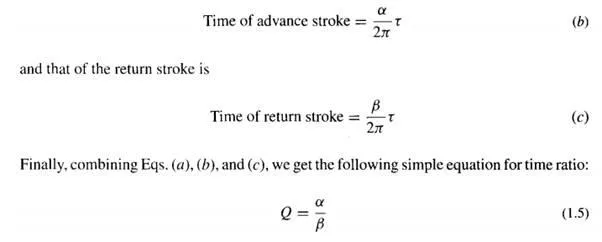
Assuming that the driving motor operates at constant speed, it is easy to find the time ratio. As shown in Fig. 1.12a, the first thing is to determine the two crank positions ABl and AB2, which mark the beginning and end of the working stroke. Next, noticing the direction of rotation of the crank, we can measure the crank angle a travelled through during the advance stroke and the remaining crank angle f3 of the return stroke. Then, if the period of the motor is T, the time of the advance stroke is
Notice that the time ratio of a quick-return mechanism does not depend on the amount of work being done or even on the speed of the driving motor. It is a kinematic property of the mechanism itself and can be found strictly from the geometry of the device.
We also notice, however, that there is a proper and an improper direction of rotation for such a device. If the motor were reversed in the example of Fig. 1.12a, the roles of a and f3 would also reverse and the time ratio would be less than I. Thus the motor must rotate counter clockwise for this mechanism to have the quick-return property.
Many other mechanisms can be found with quick-return characteristics. Another example is the Whitworth mechanism, also called the crank-shaper mechanism, shown in Figs. 1.12c and 1.12d. Although the determination of the angles a and f3 is different for each mechanism, Eq. (1.5) applies to all.
Figure 1.14a shows a six-bar linkage derived from the crank-and-rocker linkage of Fig. 1.11c by expanding coupler 3 and adding coupler 5 and slider 6. Coupler point C should be located so as to produce the desired motion characteristic of slider 6.
A crank-driven toggle mechanism is shown in Fig. 1.14b. With this mechanism, a high mechanical advantage is obtained at one end of the stroke of slider 6. The synthesis of a
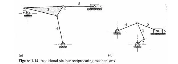
quick-return mechanism, as well as mechanisms with other properties.
Reversing Mechanisms When a mechanism is desired which is capable of delivering output rotation in either direction, some form of reversing mechanism is required. Many such devices make use of a two-way clutch that connects the output shaft to either of two drive shafts turning in opposite directions. This method is used in both gear and belt drives and does not require that the drive be stopped to change direction. Gear-shift devices, as in automotive transmissions, are also in quite common use.
Couplings and Connecters
Couplings and connectors are used to transmit motion between coaxial, parallel, intersecting, and skewed shafts. Gears of one kind or another can be used for any of these situations.
Flat belts can be used to transmit motion between parallel shafts. They can also be used between intersecting or skewed shafts if guide pulleys, as shown in Fig. 1.1Sa, are used. When parallel shafts are involved, the belts can be open or crossed, depending on the direction of rotation desired.
Figure 1.1Sb shows the four-bar drag-link mechanism used to transmit rotary motion between parallel shafts. Here crank 2 is the driver and link 4 is the output. This is a very
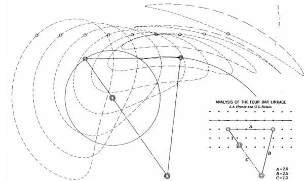
Figure 1.18 A set of couple curves
Straight-Line Generators
In the late seventeenth century, before the development of the milling machine, it was extremely difficult to machine straight, flat surfaces. For this reason, good prismatic pairs without backlash were not easy to make. During that era, much thought was given to the problem of attaining a straight-line motion as a part of the coupler curve of a linkage having only revolute connections. Probably the best-known result of this search is the straight-line mechanism developed by Watt for guiding the piston of early steam engines. Figure 1.19a shows Watt's linkage to be a four-bar linkage developing an approximate straight line as a part of its coupler curve. Although it does not generate an exact straight line, a good approximation is achieved over a considerable distance of travel.
Another four-bar linkage in which the tracing point P generates an approximate straight-line coupler-curve segment is Roberts' mechanism (Fig. 1.19b). The dashed lines in the figure indicate that the linkage is defined by forming three congruent isosceles triangles; thus BC = AD/2.
The tracing point P of the Chebyshev linkage in Fig. 1.19c also generates an approximate straight line. The linkage is formed by creating a 3-4-5 triangle with link 4 in the vertical position as shown by the dashed lines; thus DB' = 3, AD = 4, and AB' = 5. Because AB = DC, we have DC' = 5 and the tracing point P' is the midpoint of link BC. Note that D P' C also forms a 3-4-5 triangle and hence that P and P' are two points on a straight line parallel to AD.
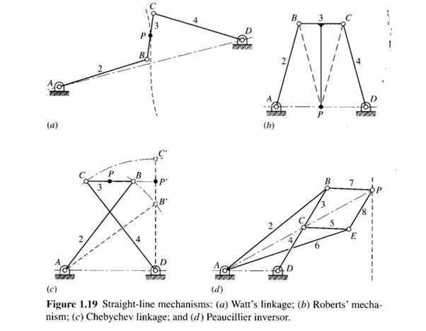
Yet another mechanism that generates a straight-line segment is the Peaucillier inversor shown in Fig. 1.19d. The conditions describing its geometry are that B C = B P = EC = E P and AB = AE such that, by symmetry, points A, C, and P always lie on a straight line passing through A. Under these conditions AC . A P = k, a constant, and the curves generated by C and P are said to be inverses of each other. If we place the other fixed pivot D such that AD = CD, then point C must trace a circular arc and point P will follow an exact straight line. Another interesting property is that if A D is not equal to CD, point P can be made to trace a true circular arc of very large radius.
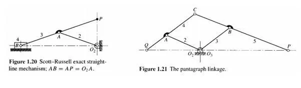
Figure 1.20 shows an exact straight-line mechanism, but note that it employs a slider. The pentagraph of Fig. 1.21 is used to trace figures at a larger or smaller size. If, for example, point P traces a map, then a pen at Q will draw the same map at a smaller scale. The dimensions 02A, AC, C B, B03 must conform to an equal-sided parallelogram.
Torfason also includes robots, speed-changing devices, computing mechanisms~/unction generators, loading mechanisms, and transportation devices in his classification. ~any of these utilize arrangements of mechanisms already presented. Others will appear in some of the chapters to follow.