
Coupler-CURVE SYNTHESIS
In this section we use the method of point-position reduction to synthesize a four-bar linkage so that a tracing point on the coupler will trace a previously specified path when the linkage is moved. Then, in sections to follow we will discover that paths having certain characteristics are particularly useful in synthesizing linkages having dwells of the output member for certain periods of rotation of the input member
In synthesizing a linkage to generate a path, we can choose up to six precision positions along the path. If the synthesis is successful, the tracing point will pass through each precision position. The final result mayor, because of the branch or order defects, may not approximate the desired path.
Two positions of a four-bar linkage are shown in Fig. 11.16. Link 2 is the input member; it is connected at A to coupler 3, containing the tracing point C, and connected to output link 4 at B. Two phases of the linkage are illustrated by the subscripts 1 and 3. Points CI and C3 are two positions of the tracing point on the path to be generated. In this example, C, and C3 have been especially selected so that the midnormal Cl3 passes through 04. Note, for the selection of points, that the angle C1 04C3 is the same as the angle Al 04A3, as indicated in the figure.
The advantage of making these two angles equal is that when the linkage is finally synthesized, the triangles C3A304 and CIA 104 are congruent. Thus, if the tracing point is made to pass through C, on the path, it will also pass through C3.
To synthesize a linkage so that the coupler will pass through four precision positions, we locate any four points CI, C2, C3, and C4 on the desired path (see Fig. 11.l7). Choosing CI and C3 say, we first locate 04 anywhere on the midnormal C13.Then, with 04 as a center and any radius R, we construct a circular arc. Next, with centers at Cl and C3, and any other radius r, we strike arcs to intersect the arc of radius R. These two intersections define points Al and A3 on the input link. We construct the midnormal al3 to AIA3 and note that it passes through 04. We locate 02 anywhere on al3. This provides an opportunity to choose a convenient length for the input rocker. Now we use 02 as a center and draw the crank circle through Al and A3. Points A2 and A4 on this circle are obtained by striking arcs of radius r again about C2 and C4. This completes the first phase of the synthesis; we have located 02 and 04 relative to the desired path and hence defined the distance 0204. We have also defined the length of the input member and located its positions relative to the four precision points on the path.
Our next task is to locate point B, the point of attachment of the coupler and output member. Anyone of the four locations of B can be used; in this example we use the B I position.
Before beginning the final step, we note that the linkage is now defined. Four arbitrary decisions were made: the location of 04, the radii Rand r, and the location of O2 . Thus an infinite number of solutions are possible.
Referring to Fig. 11.18, locate point 2 by making triangles C2A204 and C,AI2 congruent. Locate point 4 by making C4A, 04 and C, A ,4 congruent. Points 4,2, and 04 lie on a circle whose center is B,. So B, is found at the intersection of the midnormals of 0 4 2 and 044. Note that the procedure used causes points I and 3 to coincide with 04 . With Bl located, the links can be drawn in place and the mechanism tested to see how well it traces the prescribed path.
To synthesize a linkage to generate a path through five precision points, it is possible to make two-point reductions. Begin by choosing five points, C1 to Cs , on the path to be traced. Choose two pairs of these for reduction purposes. In Fig. 11.19 we choose the pairs C1 Cs and C2C3. Other pairs that could have been chosen are
Construct the perpendicular bisectors C23 and CIS of the lines connecting each pair. These intersect at point 04.Note that 04 can, therefore, be located conveniently by a judicious choice of the pairs to be used as well as by the choice of the positions of the points C; on the path.
The next step is best performed by using a sheet of tracing paper as an overlay. Secure the tracing paper to the drawing and mark upon it the center 04 , the midnormal C23, and another line from 04 to C2. Such an overlay is shown in Fig. 11.20a with the line 04C2 designated as 04C~, This defines the angle ¢23/2. Now rotate the overlay about the point 04 until the midnormal coincides with CIS and repeat for point C,. This defines the angle ¢ls/2 and the corresponding line 04C;,
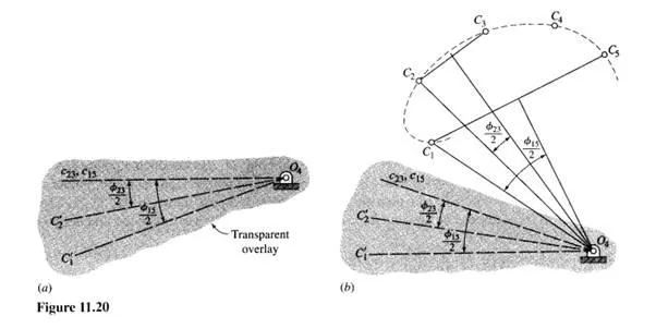
Now pin the overlay at point 04, using a thumbtack, and rotate it until a good position is found. It is helpful to set the compass for some convenient radius r and draw circles about each point Ci . The intersection of these circles with the lines 04C; and 04C; on the overlay, and with each other, will reveal which areas will be profitable to investigate. See Fig. 11.20b.
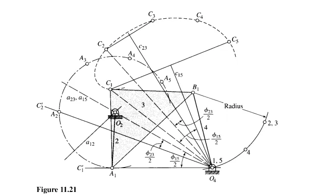
The final steps in the solution are shown in Fig. 11.21. Having located a good position for the overlay, transfer the three lines to the drawing and remove the overlay. Now draw a circle of radius r to intersect 04C; and locate point A ,. Another arc of the same radius r from point Cz intersects 04C~ at point Az. With Al and Azlocated, draw the midnormal al2; it intersects the midnormal aZ3 at Oz, giving the length of the input rocker. A circle through A I about Oz will contain all the design positions of point A; use the same radius r and locate A3, A4, and As on arcs about and C3, C4, and Cs.
We have now located everything except point BI , and this is found as before. A double point 2, 3 exists because of the choice of point 04 on the midnormal CZ3. To locate this point, strike an arc from CI of radius CZ04.
Then strike another arc from A] of radius Az 04.These intersect at point 2, 3. To locate point 4, strike an arc from CI of radius C4 04, and another from Al of radius A404. Note that point 04 and the double points 1,5 are coincident because the synthesis is based on inversion on the 04BI position. Points 04,4 and double points 2, 3 lie on a circle whose center is BI, as shown in Fig. 11.21. The linkage is completed by drawing the coupler link and the follower link in the first design position.