Adders and Differentials
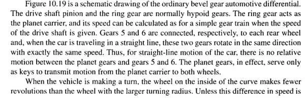
accommodated in some manner, one or both of the tires must slip in order to make the turn. The differential permits the two wheels to rotate at different angular velocities while, at the same time, delivering power to both. During a turn, the planet gears rotate about their own axes, thus permitting gears 5 and 6 to revolve at different angular velocities.
The purpose of the differential is to allow different speeds for the two driving wheels. In the usual differential of a rear-wheel drive passenger car, the torque is divided equally whether the car is traveling in a straight line or on a curve. Sometimes the road conditions are such that the tractive effort developed by the two wheels is unequal. In such a case the total tractive effort is only twice that at the wheel having the least traction, because the differential divides the torque equally. If one wheel happens to be resting on snow or ice, the total tractive effort possible at that wheel is very small because only a small torque is required to cause the wheel to slip. Thus the car sits stationary with one-wheel spinning and the other at rest with only trivial tractive effort. If the car is in motion and encounters slippery surfaces, then all traction as well as control is lost!
Limited Slip Differential
It is possible to overcome this disadvantage of the simple bevel gear differential by adding a coupling unit that is sensitive to wheel speeds. The object of such a unit is to cause more of the torque to be directed to the slower moving wheel. Such a combination is then called a limited slip differential.
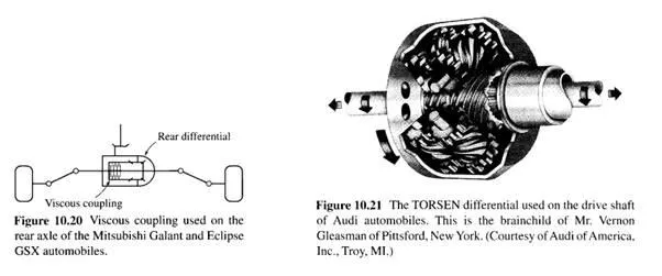
Mitsubishi, for example, utilizes a viscous coupling unit, called a VCU, which is torque-sensitive to wheel speeds. A slight difference in wheel speeds causes slightly more torque to be delivered to the slower moving wheel. A large difference, perhaps caused by the spinning of one wheel on ice, causes a large amount of torque to be delivered to the non-spinning wheel. The arrangement, as used on the rear axle of an automobile, is shown in Fig. 10.20.
Another approach is to employ Coulomb friction, or clutching action, in the coupling. Such a unit, as with the VCU, is engaged whenever a significant difference in wheel speeds occurs.
Of course, it is also possible to design a bevel gear differential that is capable of being locked by the driver whenever dangerous road conditions are encountered. This is equivalent to a solid axle and forces both wheels to move at the same speed. It seems obvious that such a differential should not be locked when the tires are on dry pavement, because of excessive wear caused by tire slipping.
Worm Gear Differential
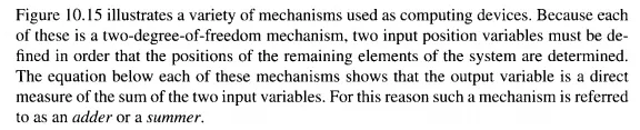
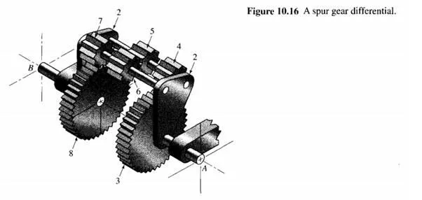
If gears 3 and 8 in Fig. 10.16 were replaced with worm gears, and planet gears 4 and 7 with mating worm wheels, then the result is a worm gear differential. Of course, planet carrier 2 would have to rotate about a new axis perpendicular to the axle A B, because worm and worm wheel axes are at right angles to each other. Such an arrangement can provide the traction of a locked differential or solid axle without the penalty of restricting differential movement between the wheels.
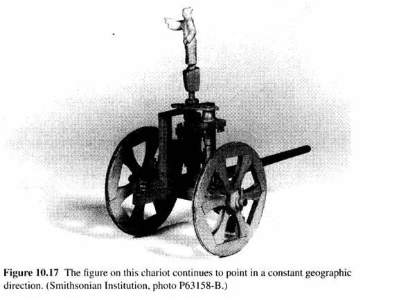
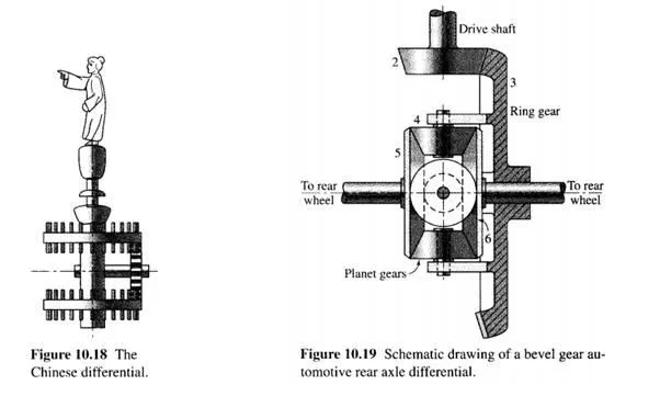
The worm gear differential was invented by Mr. Vernon Gleasman and developed by the Gleason Works as the TORS EN differential, a registered trademark now owned by TK Gleason, Inc. The word TORSEN combines parts of the words "torque-sensing" because the differential can be designed to provide any desired locking value by varying the lead angle of the worm. Figure 10.21 illustrates a TORS EN differential as used on Audi automobiles.