Nonstandard Gear Teeth
In this section we examine the effects obtained by modifying such things as pressure angle, tooth depth, addendum, or center distance. Some of these modifications do not eliminate interchangeability; all of them are made with the intent of obtaining improved performance.
The designer is often under great pressure to produce gear designs that are small and yet will transmit large amounts of power. Consider, for example, a gearset that must have a 4: I velocity ratio. If the smallest pinion that will carry the load has a pitch diameter of 2 in, the mating gear will have a pitch diameter of 8 in, making the overall space required for the two gears more than 10 in. On the other hand, if the pitch diameter of the pinion can be reduced by only ~ in the pitch diameter of the gear is reduced by a full I in and the overall size of the gearset is reduced by I ~ in. This reduction assumes considerable importance when it is realized that the sizes of associated machine elements, such as shafts, bearings, and enclosures, are also reduced. If a tooth of a certain pitch is required to carry the load, the only method of decreasing the pinion diameter is to use fewer teeth. However, we have already seen that problems involving interference, undercutting, and contact ratio are encountered when the tooth numbers are made too small. Thus the three principal reasons for employing nonstandard gears are to eliminate undercutting, to prevent interference, and to maintain a reasonable contact ratio. It should be noted too that, if a pair of gears is manufactured of the same material, the pinion is the weaker and is subject to greater wear because its teeth are in contact a greater portion of the time. Then, any undercutting weakens the tooth that is already the weaker of the two. Thus, another objective of nonstandard gears is to gain a better balance of strength between the pinion and the gear.
As an involute curve is generated from its base circle, its radius of curvature becomes larger and larger. Near the base circle the radius of curvature is quite small, being exactly zero at the base circle. Contact near this region of sharp curvature should be avoided if possible because of the difficulty of obtaining good cutting accuracy in areas of small curvature, and because the contact stresses are likely to be very high. Nonstandard gears present the opportunity of designing to avoid these sensitive areas. Clearance Modifications A larger fillet radius at the root of the tooth increases the fatigue strength of the tooth and provides extra depth for shaving the tooth profile. Because interchangeability is not lost, the clearance is sometimes increased to 0.300/ P or 0.400/ P to obtain space for a larger fillet radius.
Center-Distance Modifications When gears of low tooth numbers are to be paired with each other, or with larger gears, reduction in interference and improvement in the contact ratio can be obtained by increasing the center distance. Although such a system changes the tooth proportions and the pressure angle of the gears, the resulting tooth shapes can be generated with rack cutters (or hobs) of standard pressure angles or with standard pinion shapers. Before introducing this system, it will be of value to develop additional relations about the geometry of gears.
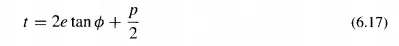
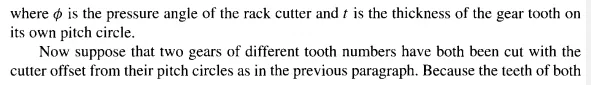
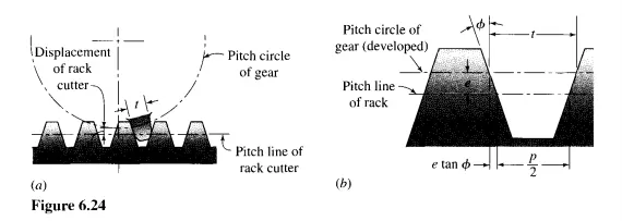
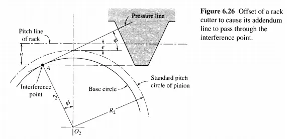
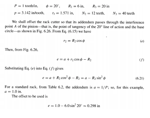
The first new relation is for finding the thickness of a tooth that is cut by a rack cutter (or hob) when the pitch line of the rack cutter has been displaced or offset a distance e from the pitch circle of the gear being cut. What we are doing here is moving the rack cutter away from the center of the gear being cut. Stated another way, suppose the rack cutter does not cut as deeply into the gear blank and the teeth are not cut to full depth. This produces teeth that are thicker than the standard, and this thickness will now be found. Figure 6.24a shows the problem, and Fig. 6.24b shows the solution. The increase of tooth thickness at the pitch circle is 2e tan so that
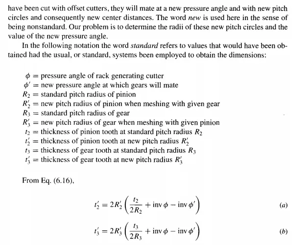
are brought into contact. Bringing a pair of gears into contact creates a pair of pitch circles that are tangent to each other at the pitch point. Throughout this discussion, the idea of a pair of so-called standard pitch circles has been used in order to define a certain point on the involute curves. These standard pitch circles, we have seen, are the ones that would come into existence when the gears are paired if the gears are not modified from the standard dimensions. On the other hand, the base circles are fixed circles that are not changed by tooth modifications. The base circle remains the same whether the tooth dimensions are changed or not; so we can determine the base circle radius using either the standard pitch circle or the new pitch circle. Thus, from Eq. (6.15),
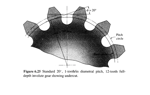
system, interference is severe whenever the number of teeth is less than 14. The resulting undercutting is evident in the drawing. If this pinion were mated with a standard 40-tooth gear, the contact ratio would be 1.41, which can easily be verified by Eq. (6.9).
In an attempt to eliminate the undercutting, improve the tooth action, and increase the contact ratio, let the 12-tooth pinion be cut from a larger blank. Then let the resulting pinion be paired again with the 40-tooth standard gear and let us determine the degree of improvement. If we designate the pinion as subscript 2 and designate the gear as 3, the following values are found

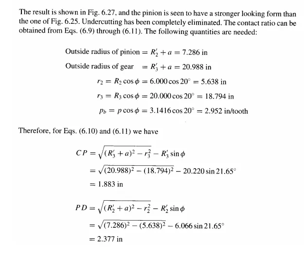

Thus, the contact ratio has increased only slightly. The modification, however, is justified because of the elimination of undercutting which results in a very substantial improvement in the strength of the teeth.
Long-and-Short-Addendum Systems It often happens in the design of machinery that the center distance between a pair of gears is fixed by some other design consideration or feature of the machine. In such a case, modifications to obtain improved performance cannot be made by varying the center distance.
In the previous section we saw that improved action and tooth shape can be obtained by backing out the rack cutter from the gear blank during forming of the teeth. The effect of this withdrawal is to create the active tooth profile farther away from the base circle. Examination of Fig. 6.27 reveals that more dedendum could be used on the gear (not the pinion) before the interference point is reached. If the rack cutter is advanced into the gear blank by a distance equal to the offset from the pinion blank, more of the gear dedendum will be used and at the same time the center distance will not be changed. This is called the long-and-short-addendum system.
In the long-and-short-addendum system there is no change in the pitch circles and consequently none in the pressure angle. The effect is to move the contact region away from the pinion center toward the gear center, thus shortening the approach action and lengthening the recess action.
The characteristics of the long-and-short-addendum system can be explained by reference to Fig. 6.28. Figure 6.28a illustrates a conventional (standard) set of gears having a dedendum equal to the addendum plus the clearance. Interference exists, and the tip of the gear tooth will have to be relieved as shown or the pinion will be undercut. This is so because the addendum circle crosses the line of action at C, outside of the tangency or interference point A; hence, the distance A C is a measure of the degree of interference.
To eliminate the undercutting or interference, the pinion addendum may be enlarged, as in Fig. 6.28b until the addendum circle of the pinion passes through the interference point (point B) of the gear. In this manner we shall be using all of the gear-tooth profile. The same whole depth may be retained; hence the dedendum of the pinion may be reduced by the same amount that the addendum is increased. This means that we must also lengthen the gear dedendum and shorten the dedendum of the mating pinion. With these changes the path of contact is the line CD of Fig. 6.27 b. It is longer than the path A D of Fig. 6.28a, and so the contact ratio is higher. Notice too that the base circles, the pitch circles, the pressure angle, and the center distance have not changed. Both gears can be cut with standard cutters by advancing the cutter into the gear blank, for this modification, by a distance equal to the amount of withdrawal from the pinion blank. Finally, note that the blanks from which the pinion and gear are cut must now be of different diameters than the standard blanks.
The tooth dimensions for the long-and-short-addendum system can be determined by using the equations developed in the previous sections.
A less obvious advantage of the long-and-short-addendum system is that more recess action than approach action is obtained. The approach action of gear teeth is analogous to pushing a piece of chalk across a blackboard; the chalk screeches. But when the chalk is pulled across a blackboard, analogous to the recess action, it glides smoothly. Thus, recess action is always preferable because of the smoothness and the lower frictional forces.