Plate CAM with Reciprocating Roller Follower
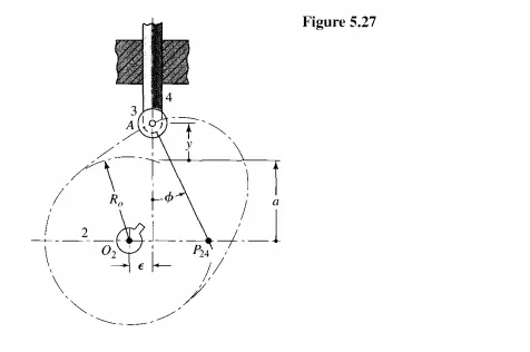
Figure 5.27 shows a plate cam with a reciprocating roller follower. We see that three geometric parameters remain to be chosen after the displacement diagram is completed and before the cam layout can be accomplished. These three parameters are: the radius of the prime circle Ro, the eccentricity £, and the radius of the roller Rr. There are also two potential problems to be considered when choosing these parameters. One problem is undercutting and the other is an improper pressure angle.
Pressure angle is the name used for the angle between the axis of the follower stem and the line of the force exerted by the cam onto the roller follower, the normal to the pitch curve through the trace point. The pressure angle is labelled ¢in Figure 5.27. Only the component of force along the line of motion of the follower is useful in overcoming the output load; the perpendicular component should be kept low to reduce sliding friction between the follower and its guideway. Too high a pressure angle increases the deleterious effect of friction and may cause the translating follower to chatter or perhaps even to jam. Cam pressure angles of up to about 30° to 35° are about the largest that can be used without causing difficulties.
In Fig. 5.27 we see that the normal to the pitch curve intersects the horizontal axis at point P24-that is, at the instantaneous center of velocity between cam 2 and follower 4. Because the follower is translating, all points of the follower have velocities equal to that of P24.This velocity must also be equal to the velocity of the coincident point of link 2; that is,
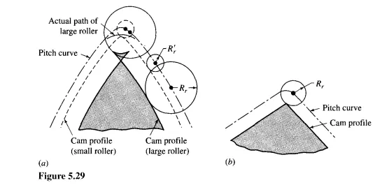
Even though the prime circle has been sized to give a satisfactory pressure angle, the follower may still not complete the desired motion; if the curvature of the pitch curve is too sharp, the cam profile may be "undercut." Figure 5.29a shows a portion of a cam pitch curve and two cam profiles generated by two different-size rollers. The cam profile generated by the larger roller is undercut and intersects itself. The result, after machining, is a pointed cam that does not produce the desired motion. It is also clear from the same figure that a smaller roller moving on the same pitch curve generates a satisfactory cam profile. Similarly, if the prime circle and thus the cam size is increased enough, the larger roller will also operate satisfactorily.
In Fig. 5.29b we see that the cam profile will be pointed when the roller radius Rr is equal to the radius of curvature of the pitch curve. Therefore, to achieve some chosen minimum value Pmin for the minimum radius of curvature of the cam profile, the radius of