Plate CAM with Reciprocating Flat-Face Follower
Once the displacement diagram of a earn system has been completely determined, as described in Section 5.8, the layout of the actual earn shape can be made, as shown in Section 5.4. In laying out the earn, however, we recall the need for a few more parameters, depending on the type of earn and follower-for example, the prime-circle radius, any offset distance, roller radius, and so on. Also, as we will see, each different type of earn can be subject to certain further problems unless these remaining parameters are properly chosen.
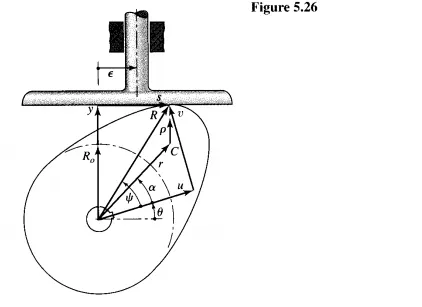
In this section we study the problems that may be encountered in the design of a plate earn with a reciprocating flat-face follower. The geometric parameters of such a system that may yet be chosen are the prime-circle radius Ro, the offset (or eccentricity) to of the follower stem, and the minimum width of the follower face.
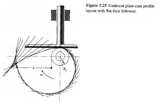
Figure 5.25 shows the layout of a plate earn with a radial reciprocating flat-face follower. In this case the displacement chosen was a cycloidal rise of L = 100 mm during /31 = 90° of earn rotation, followed by a cycloidal return during the remaining /32 = 270° of earn rotation. The layout procedure of Fig. 5.10 was followed to develop the earn shape, and a prime-circle radius of Ro = 25 mm was used. Obviously, there is a problem because the earn profile intersects itself. In machining, part of the earn shape would be lost and during operation the intended cycloidal motion would not be achieved. Such a earn is said to be undercut. Why did undercutting occur in this example, and how can it be avoided? It resulted from attempting to achieve too great a lift in too little earn rotation with too small a earn.