High-Speed CAMS
Continuing with our discussion of parabolic motion, let us consider briefly the implications of the "acceleration" curve of Fig. 5.12 on the dynamic performance of the cam system. Any real follower must, of course, have some mass and, when multiplied by acceleration, will exert an inertia force (see Chapter IS). Therefore, the "acceleration" curve of Fig. 5.12 can also be thought of as indicating the inertia force of the follower, which, in turn, must be felt at the follower bearings and at the contact point with the cam surface. An "acceleration" curve with abrupt changes, such as parabolic motion, will exert abruptly changing contact stresses at the bearings and on the cam surface and lead to noise, surface wear, and eventual failure. Thus it is very important in choosing a displacement diagram to ensure that the first- and second-order kinematic coefficients (i.e., the "velocity" and "acceleration" curves) are continuous-that is, that they contain no step changes.
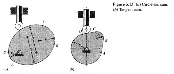
Sometimes in low-speed applications compromises are made with the velocity and acceleration relationships. It is sometimes simpler to employ a reverse procedure and design the cam shape first, obtaining the displacement diagram as a second step. Such cams are often composed of some combination of curves such as straight lines and circular arcs, which are readily produced by machine tools. Two examples are the circle-arc earn and the tangent earn of Fig. 5.13. The design approach is by iteration. A trial cam is designed, and its kinematic characteristics computed. The process is then repeated until a cam with acceptable characteristics is obtained. Points A, B, C, and D of the circle-arc cam and the tangent cam are points of tangency or blending points. It is worth noting, as with the
parabolic-motion example before, that the acceleration changes abruptly at each of the blending points because of the instantaneous change in radius of curvature.
Although cams with discontinuous acceleration characteristics are sometimes found in low-speed applications, such cams are certain to exhibit major problems if the speed is raised. For any high-speed earn application, it is extremely important that not only the displacement and "velocity" curves but also the "acceleration" curve be made continuous for the entire motion cycle. No discontinuities should be allowed at the boundaries of different sections of the earn.
As shown by Eq. (5.17), the importance of continuous derivatives becomes more serious as the camshaft speed is increased. The higher the speed, the greater the need for smooth curves. At very high speeds it might also be desirable to require that jerk, which is related to rate of change of force, and perhaps even higher derivatives, be made continuous as well. In most applications, however, this is not necessary.
There is no simple answer as to how high a speed one must have before considering the application to require high-speed design techniques. The answer depends not only on the mass of the follower but also on the stiffness of the return spring, the materials used, the flexibility of the follower, and many other factors.' Further analysis techniques on earn dynamics are presented in Chapter 20. Still, with the methods presented below, it is not difficult to achieve continuous derivative displacement diagrams. Therefore, it is recommended that this be undertaken as standard practice. Parabolic-motion cams are no easier to manufacture than cycloidal-motion cams, for example, and there is no good reason for their use. The circle-arc earn and the tangent earn are easier to produce; but with modem machining methods, cutting of more complex earn shapes is not expensive.
Kinematic Coefficients of the follower motion