Graphical Layout of CAM profiles
Let us now examine the problem of determining the exact shape of a cam surface required to deliver a specified follower motion. We assume here that the required motion has been completely defined-graphically, analytically, or numerically-as discussed in later sections. Thus a complete displacement diagram can be drawn to scale for the entire cam rotation. The problem now is to layout the proper cam shape to achieve the follower motion represented by this displacement diagram.
We illustrate the procedure using the case of a plate cam as shown in Fig. 5.8. Let us first note some additional nomenclature shown in this figure.
The trace point is a theoretical point of the follower; it corresponds to the tip of a fictitious knife-edge follower. It is located at the center of a roller follower or along the surface of a flat-face follower.
The pitch curve is the locus generated by the trace point as the follower moves relative to the cam. For a knife-edge follower, the pitch curve and cam surface are identical. For a roller follower they are separated by the radius of the roller.
The prime circle is the smallest circle that can be drawn with center at the cam rotation axis and tangent to the pitch curve. The radius of this circle is denoted as Ra. The base circle is the smallest circle centered on the cam rotation axis and tangent to the cam surface. For a roller follower it is smaller than the prime circle by the radius of the roller, and for a flat-face follower it is identical with the prime circle.
In constructing the cam profile, we employ the principle of kinematic inversion. We imagine the sheet of paper on which we are working to be fixed to the cam, and we allow the follower to appear to rotate opposite to the actual direction of cam rotation. As show) in Fig. 5.8, we divide the prime circle into a number of segments and assign station numbers to the boundaries of these segments. Dividing the displacement-diagram abscissa into corresponding segments, we transfer distances, by means of dividers, from the displacement diagram directly onto the cam layout to locate the corresponding positions of the trace point. The smooth curve through these points is the pitch curve. For the case of a roller follower, as in this example, we simply draw the roller in its proper position at each station and then construct the cam profile as a smooth curve tangent to all these roller positions.
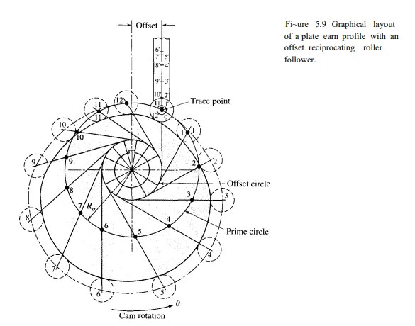
Figure 5.9 shows how the method of construction must be modified for an offset roller follower. We begin by constructing an offset circle, using a radius equal to the amount of
the offset. After identifying station numbers around the prime circle, the centerline of the follower is constructed for each station, making it tangent to the offset circle. The roller centers for each station are now established by transferring distances from the displacement diagram directly to these follower centerlines, always measuring positive outward from the prime circle. An alternative procedure is to identify the points 0', 1', 2', and so on, on a single follower centerline and then to rotate them about the cam center to the corresponding follower centerline positions. In either case, the roller circles can be drawn next and a smooth curve tangent to all roller circles is the required cam profile.
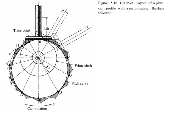
Figure 5.1 0 shows the construction for a plate cam with a reciprocating flat-face follower. The pitch curve is constructed by using a method similar to that used for the roller follower in Fig. 5.8. A line representing the flat face of the follower is then constructed in each position. The cam profile is a smooth curve drawn tangent to all the follower positions. It may be helpful to extend each straight line representing a position of the follower face to form a series of triangles. If these triangles are lightly shaded, as suggested in the illustration, it may be easier to draw the cam profile inside all the shaded triangles and tangent to the inner sides of the triangles.
Figure 5.11 shows the layout of the profile of a plate cam with an oscillating roller follower. In this case we must rotate the fixed pivot center of the follower opposite the direction of cam rotation to develop the cam profile. To perform this inversion, first a circle is drawn about the camshaft center through the fixed pivot of the follower. This circle is then divided and given station numbers to correspond to the displacement diagram. Next arcs are drawn about each of these centers, all with equal radii corresponding to the length of the follower.
In the case of an oscillating follower, the ordinate values of the displacement diagram represent angular movements of the follower. If the vertical scale of the displacement
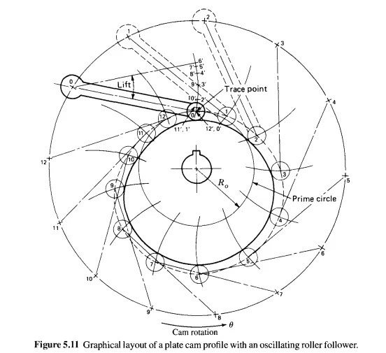
diagram is properly chosen initially, however, and if the total lift of the follower is a reasonably small angle, ordinate distances of the displacement diagram at each station can be transferred directly to the corresponding arc travelled by the roller by using dividers and measuring positive outward along the arc from the prime circle to locate the center of the roller for that station. Finally, circles representing the roller positions are drawn at each station, and the cam profile is constructed as a smooth curve tangent to each of these roller positions.
From the examples presented in this section, it should be clear that each different type of cam-and-follower system requires its own method of construction to determine the cam profile graphically from the displacement diagram. The examples presented here are not intended to be exhaustive of those possible, but they illustrate the general approach. They should also serve to illustrate and reinforce the discussion of the previous section; it should now be clear that much of the detailed shape of the cam itself results directly from the shape of the displacement diagram. Although different types of cams and followers have different shapes for the same displacement diagram, once a few parameters (such as prime-circle radius) are chosen to determine the size of a cam, the remainder of its shape results directly from the motion requirements specified in the displacement diagram.