Displacement Diagrams
In spite of the wide variety of cam types used and their differences in form, they also have certain features in common which allow a systematic approach to their design. Usually a cam system is a single-degree-of-freedom device. It is driven by a known input motion, usually a shaft that rotates at constant speed, and it is intended to produce a certain desired periodic output motion for the follower.
In order to investigate the design of cams in general, we will denote the known input motion by aCt) and the output motion by y. Reviewing Figs. 5.1 to 5.3 will demonstrate the definitions of y and a for various types of cams. These figures also show that y is a translational distance for a reciprocating follower but is an angle for an oscillating follower.
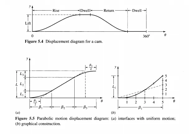
During the rotation of the cam through one cycle of input motion, the follower executes a series of events as shown in graphical form in the displacement diagram of Fig. 5.4. In such a diagram the abscissa represents one cycle of the input motion a (one revolution of the cam) and is drawn to any convenient scale. The ordinate represents the follower travel y and for a reciprocating follower is usually drawn at full scale to help in the layout of the cam. On a displacement diagram it is possible to identify a portion of the graph called the rise, where the motion of the follower is away from the cam center. The maximum rise is called the lift. Portions of the cycle during which the follower is at rest are referred to as dwells, and the return is the portion in which the motion of the follower is toward the cam center.
Many of the essential features of a displacement diagram, such as the total lift or the placement and duration of dwells, are usually dictated by the requirements of the application. There are, however, many possible choices of follower motions that might be used for the rise and return, and some are preferable to others depending on the situation. One of the
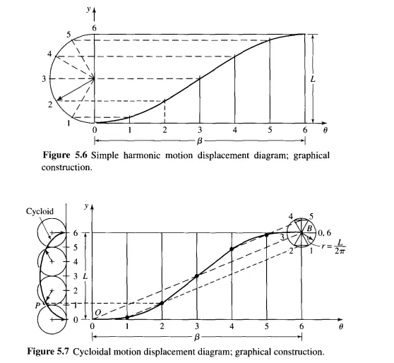
A point P of the circle, originally located at the origin, traces a cycloid as shown. As the circle rolls without slip at a constant rate, the graph of the point's vertical position y versus rotation angle gives the displacement diagram shown at the right of the figure. We find it much more convenient for graphical purposes to draw the circle only once, using point B as a center. After dividing the circle and the abscissa into an equal number of parts and numbering them as shown, we can project each point of the circle horizontally until it intersects the ordinate; next, from the ordinate, we project parallel to the diagonal 0 B to obtain the corresponding point on the displacement diagram.