Dynamic Circuits
Introduction to Dynamic Gates
Static logic is great for its robustness. However, it is too slow to meet requirements for high speed processor critical paths. Thus, designers are increasingly turning to dynamic logic in hopes of achieving a 1.5 - 2x speedup over static gates. The main drawback of static gates is the fact that inputs must drive both NMOS and PMOS transistors. Only one of the two transistors is ever on, meaning that the input capacitance of the other transistor loads the critical path without increasing the current drive of the gate. Moreover, the PMOS transistors must be large and thus add much capacitance.
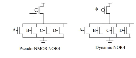
If we could construct gates which only have NMOS transistors in the critical path, circuits would run much faster. Pseudo-NMOS logic achieves this goal by replacing the PMOS stack with a single grounded PMOS transistor serving as a resistive pullup. Thus, the NMOS pulldowns can be very fast. Unfortunately, the PMOS transistor fights against the NMOS during a falling transition, slowing the fall time.
Also, it must be weaker than the NMOS, so the rise time is not very good. Finally, when the output is low, there is a path from VDD to GND wasting power. An alternative scheme is to connect the PMOS transistor to a clock, instead of ground. This topology is called a dynamic gate. Figure 1 shows the similarity between dynamic logic and pseudo-NMOS gates.
FIGURE 1. Pseudo-NMOS and Dynamic gates
Dynamic Circuits
November 4, 1997 2 / 15 Dynamic gates operate in two phases: precharge and evaluation. During the precharge phase, the clock is low, turning on the PMOS device and pulling the output high. During evaluation, the clock is high, turning off the PMOS device. The output may “evaluate” low through the NMOS transistor stack.
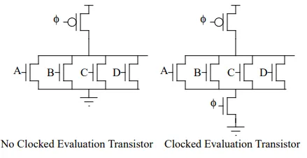
The PRECHARGE rule of dynamic gates states that there should be no active path to ground during precharge, so that the PMOS transistor can fully precharge the output high without contention with the NMOS pulldowns. Sometimes this can be achieved by guaranteeing that some inputs are low. For example, with a NOR4 gate, all four inputs must be low. For a NAND4 gate, only one of the series pulldown transistors must be low. It is not always possible to guarantee this condition, so often an extra clocked evaluation transistor is placed at the bottom of the pulldown stack, as shown in Figure 2.
FIGURE 2. Dynamic gates with and without clocked evaluation transistors
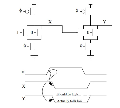
Another limitation of dynamic gates arises when one dynamic gate directly drives the next, as shown in Figure 3. When φ is low, both gates precharge high. When φ rises, both gates begin evaluating. Since the first gate has a high input, its output X falls low. The second NOR gate should therefore produce a high output. Unfortunately, the second NOR gate initially received the high value at X and evaluates low. By the time X falls, Y may have become corrupted. Since the precharge transistors are off, Y has no way of recovering to the correct high value during the evaluation phase. The circuit produces an incorrect result.
FIGURE 3. Incorrect operation of cascaded dynamic gates
The problem arose because the second dynamic gate had an input switch from high to low while the gate was evaluating. The output had pulled low while the input was high, then cannot recover to a correct high value. To avoid this problem, dynamic gates must obey the MONOTONICITY rule: all inputs to dynamic gates should make only low to high transitions while the gates are evaluating. Inputs must be “monotonically rising,” meaning they can stay low, stay high, or may rise, but may not fall.
An easy way to achieve this condition is to insert an inverting static gate between each dynamic gate, as shown in Figure 4. Now the gate operates correctly. The dynamic/static gate pair is called a domino gate. All domino gates in a cycle are precharged simultaneously, like dominos being set up, then one may trigger the next which triggers the next, like a chain of dominos falling.
Domino Robustness Rules
Domino gates which obey the precharge and monotonicity rules will be logically correct. However, domino circuits are much more sensitive to noise than static circuits and therefore additional electrical rules are requires to ensure correct operation. If static gates receive too much noise, they can glitch, but eventually settle to the correct output. If dynamic gates receive too much noise, they can incorrectly evaluate and never recover.
Charge Sharing
Charge sharing is one important dynamic gate failure mode. When a dynamic gate drives a small load, the internal diffusion capacitances may become comparable to the load capacitance. If the diffusion capacitances are low when evaluation begins, they may share charge with the load capacitance, causing the output voltage to droop from the capacitive voltage divider. For example, consider the dynamic gate in Figure 6. Suppose node X is initially low, perhaps from operation in the previous cycle. Suppose after evaluation begins, input A rises, but input B stays low. The capacitance on node X will share charge with the output capacitance, resulting in a dip on the output voltage. If the ratio of charge is too large, the output will fall by more than the noise margin of the next gate and produce an incorrect result.