How to measure Baseline
In surveying procedures such as traversing, triangulation, trilateration, and setting out, baseline measurement is critical. Prior to the invention of the Electromagnetic Distance Measuring Instrument, baseline measurements were made with equipment such as tapes, chains, and bands (EDM).
The method of measuring baseline with early instruments has largely been replaced by distance measurements using electromagnetic means. So, basically there are two methods to measure the base line.
1)Conventional method
i) Wheeler’s method ii) Jadrein’s method
2)Electronic Distance Measurement
1). Conventional Method:
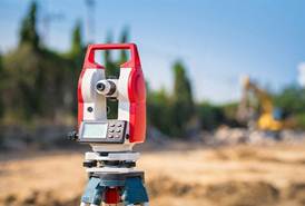
Theodolite
To use these methods, first field work is executed by two groups of surveyors. One is called setting out group consists of two surveyors and several porters, is responsible for aligning the measuring tripods prior to the measurement and at the proper intervals and the second group is called the measuring party, consisting of two observers, leveler, recorder and staff man, for actual measurements.
The obstructions are removed from the base line, which is then split into reasonable segments of up to one kilometer in length and is accurately aligned using theodolite.
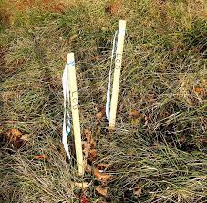
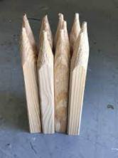
Stout posts or marking stakes are driven firmly into the ground whenever the alignment changes. The setting out party then aligns the measuring tripods in preparation for the measurement, which can be accomplished in two ways:
- Measurement on Wheeler’s method by Wheeler’s base line apparatus.
- Jaderin’s method.
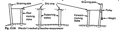
i) Wheeler’s Method:
In this method the marking stakes are driven into the ground at regular intervals (less than the length of one tape) on the base line in such a way that their tops are 50 cm above the ground.
- A 4 cm wide zinc strip is nailed on these marking stakes in order to avoid extremities of tape.
- Between these marking stakes, supporting stakes are also placed at interval of 5 to 15 meters with their faces in the line.
- The level of these supporting marking stakes must be same or on uniform grade (increasing or decreasing by constant level).
- As shown in figure, straining rods are placed. One end of tape (forward end) is attached to the weight by pulley of straining rod from where pull is applied and other end of tape is attached with spring balance at the other straining rod in order to measure this tension created by this pull.
- After this the tape at forward stake and at rear stake is adjusted to coincide with the mark on zinc strips (center of marking stake).
- The position of these coinciding points is noted and distance between these marks is measured. Temperature is noted at each marking and work continues to the next marking stake.
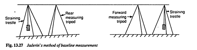
ii) Jaderin’s Method:
In this method, instead of straining poles, trestles (straining tripods) are used and measuring tripods are used in place of marking stakes.
- There are two points taken.
- Position the theodolite on one station and the ranging rod on the other.
- Between the two measuring sites, place two or three tripod stands. These tripods are placed at regular intervals.
- All the tripods are aligned (ranged) along the line.
- After aligning these tripods, ranging rod and theodolite are also replaced with tripods.
- Another theodolite is placed in the vicinity of field to check whether all the tripod stands are at same level or not. If not, then first level the tripods to proceed next.
- One end of tape is pulled by applying load and other end is attached with spring balance to measure this pull (as in wheeler’s method).
- At each stage, the temperature is recorded for temperature correction.
- Tension (pull) is created in the tape during length measurement, which is measured by the spring balance. The pull should not be more than 20 times of the weight of tape. The procedure is repeated till all base line is covered.
Corrections:
Jaderin introduced some corrections for more accurate measurements. These are as follow:
Corrections in Taping:
- When the uncorrected length must be extended in order to reach the true length, the correction is said to be plus or positive.
- When the uncorrected length must be reduced in order to reach the true length, the correction is said to be negative.
i)Correction for Absolute Length
Absolute length = Nominal Length ± Ca
Ca = L (l’ – l)/L
where:
L = Measured or Recorded Length
l = Nominal Length of a tape
l’ = Actual Length of a tape
Ca = Correction for Absolute Length
The sign of the correction is determined by l and l’ values. However, because l’ is typically more than l, this adjustment is usually positive, indicating that when a tape is stretched and is too long, it reads too short.
ii)Correction for Temperature
Ct = α(Tm-To)L
Where:
α = Coefficient of Thermal Expansion
Tm = Mean Temperature during Measurement
To = Temperature of calibration Measured Length
iii)Correction for Pull/Tension
Cp = (P – Po)L/AE
Where
P = Pull applied during
Po = Pull under which the tape was calibrated
L = Measured Length
A = Cross sectional Area of the tape
E = Modulus of Elasticity of Tape Material
iv)Correction for Sag:
Cs = w2 L3 cos2φ/(24P²)
where
P = Pull applied during measurement
φ = Angle of slope between tape supports
w = Weight of tape per unit length
W = Total Weight of Tape
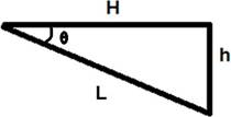
v)Correction for Slope
C = L (1 – cosφ )
OR
C = L – √(L² – h²)
C = h²/(2 L)
All these corrections are applied to the measured length in order to get accurate results.
2). Electronic Distance Measurement
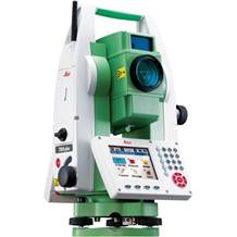
EDM total station
Only in the early 1950s the first electronic distance measuring equipment were developed. These primarily consisted of Electro-optical and electromagnetic instruments. They were bulky heavy and expensive. The typical EDM today uses the Electro-optical principle. They are small reasonably lightweight highly accurate but still expensive.
The use of EDM technology removes the requirement for extensive baseline preparation. The use of EDM greatly simplifies the baseline measurement process. Since 1950, baseline measurement using invar wires has been replaced by a far more convenient form of measurement, namely the use of Electro Magnetic Distance Measurement (EDM).
EDM reduces the requirement for time-consuming baseline preparations. The length of the baseline has no bearing on the time it takes to take the requisite instrument reading during the actual measuring procedure.