Locating Position
Establishing control networks and their subsequent computation leads to an implied rectangular coordinate system over the area surveyed. The minor control points in particular can now be used to position topographic data and control the setting out of a construction design. The methods of topographic survey and dimensional control will most probably be:
(a) by polar coordinates (distance and bearing) using a total station; or
(b) by GPS using kinematic methods.
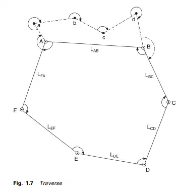
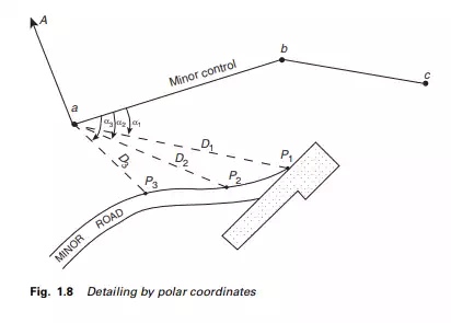
Considering method (a), a total station would be set up over a control point whose coordinates are known as ‘a’, and back-sighted to another control point ‘b’ whose coordinates are also known. Depending on the software on board, the coordinates may be keyed into the total station. Alternatively, the bearing of the line ‘ab’, computed from the coordinates, may be keyed in. Assuming the topographic position of a road is required, the total station would be sighted to a corner cube prism fixed to a detail pole held vertically at (P1), the edge of the road as shown in Figures 1.7 and 1.8. The field data would comprise the horizontal angle baP1(α1) and the horizontal distance D1 (Figure 1.8). Depending on the software being used, the angle α1 would be used to compute the bearing aP1 relative to ‘ab’ and, with the horizontal distance D1, compute the rectangular coordinates of P1 in the established coordinate system. This process is repeated for the remaining points defining the road edge and any other topographic data within range of the total station. The whole area would be surveyed in this way by occupying pairs of control points situated throughout the area.
For method (b), using GPS equipment, the methods are dealt with in detail in Chapter 9: Satellite positioning.
A further development is the integration of a total station with GPS. This instrument, produced by Leica Geosystems and called Smart Station, provides the advantages of both the systems (a) and (b).
If using existing control, the local coordinate data is copied into the smart Station and used in the usual manner on existing pairs of control points. Where the GPS cannot be used because of excessive tree cover for instance, then the total station may be used in the usual way.
Perhaps the most significant aspect of this instrument is that pairs of points for orientation as well as position could be established by GPS thereby eliminating the need to establish a prior control network, with great savings on time and money.
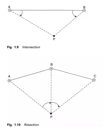
Alternative methods used very often for the location of single points are intersection, where P is fixed by measuring the horizontal angles BAP and PBA as shown in Figure 1.9, and resection (Figure 1.10). This method forms the basis of triangulation. Similarly, P could be fixed by the measurement of horizontal distances AP and BP, and forms the basis of the method of trilateration. In both these instances there is no independent check, as a position for P (not necessarily the correct one) will always be obtained. Thus at least one additional measurement is required, either by combining the angles and distances, by measuring the angle at P as a check on the angular intersection, or by producing a trisection from an extra control station.
Resection (Figure 1.10) is done by observing the horizontal angles at P to at least three control stations of known position. The position of P may be obtained by a mathematical solution as illustrated in Chapter 6. It can be seen that all the above procedures simply involve the measurement of angles and distances.