Control Networks
The establishment of two- or three-dimensional control networks is the most fundamental operation in the surveying of large or small areas of land. Control networks comprise a series of points or positions which are spatially located for the purpose of topographic surveying, for the control of supplementary points, or dimensional control on site.
The process involved in carrying out the surveying of an area, the capture and processing of the field data, and the subsequent production of a plan or map, will now be outlined briefly. The first and obvious step is to know the purpose and nature of the project for which the surveys are required in order to assess the accuracy specifications, the type of equipment required and the surveying processes involved.
For example, a major construction project may require structures, etc., to be set out to sub centimetre accuracy, in which case the control surveys will be required to an even greater accuracy. Earthwork volumes may be estimated from the final plans, hence contours made need to be plotted at 2 m intervals or less. If a plan scale of 1/500 is adopted, then a plotting accuracy of 0.5 mm would represent 0.25 m on the ground, thus indicating the accuracy of the final process of topographic surveying from the supplementary control and implying major control to a greater accuracy. The location of topographic data may be done using total stations, GPS satellites, or, depending on the extent of the area, aerial photogrammetry. The cost of a photogrammetric survey is closely linked to the contour interval required and the extent of the area. Thus, the accuracy of the control network would define the quality of the equipment and the number of observations required.
The duration of the project will affect the design of survey stations required for the control points. A project of limited duration may only require a long, stout wooden peg, driven well into solid, reliable ground and surrounded by a small amount of concrete. A fine nail in the top defines the geometrical position to be located. A survey control point designed to be of longer duration is illustrated in Chapter 6, Figure 6.15.
The next stage of the process is a detailed reconnaissance of the area in order to establish the best positions for the control points.
Initially, data from all possible sources should be studied before venturing into the field. Such data would comprise existing maps and plans, aerial photographs and any previous surveying data of that area. Longitudinal sections may be drawn from the map contours to ensure that lines of sight between control points are well above ground level and so free of shimmer or refraction effects. If the surveys are to be connected into the national surveys of the country (Ordnance Survey National Grid in the UK), then the position of as many national survey points as possible, such as (in the UK) those on the GPS Active or Passive Network, should be located. These studies, very often referred to as the ‘paper survey’, should then be followed up with a detailed field reconnaissance.
This latter process locates all existing control in the area of interest, both local and national, and establishes the final positions for all the new control required. These final positions should be chosen to ensure clear, uninterrupted lines of sight and the best observing positions. The location of these points, and the type of terrain involved, would then influence the method of survey to be used to locate their spatial position.
Figure 1.4 indicates control points A, B,…, F, in the area to be surveyed. It is required to obtain the coordinate positions of each point. This could be done using any of the following methods:
(a) Intersection or resection
(b) Traversing
(c) Networks
(d) GPS satellites
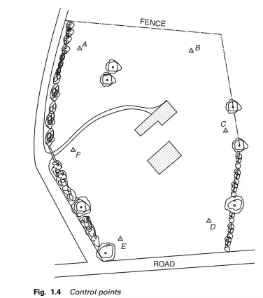
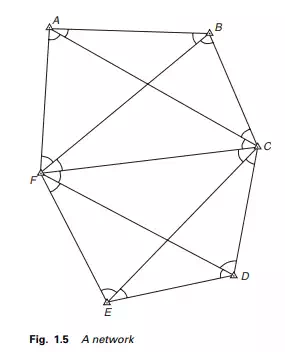
Figure 1.5 illustrates possible lines of sight. All the horizontal angles shown would be measured to the required accuracy to give the shape of the network. At least one side would need to be measured, say AB, to give the scale or size of the network. By measuring a check baseline, say ED, and comparing it with its value, computed through the network, the scale error could be assessed. This form of survey is classical triangulation and although forming the basis of the national maps of many countries, is now regarded as obsolete because of the need for lines of sight between adjacent points. Such control would now be done with GPS.
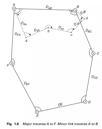
If the lengths of all the sides were measured in the same triangular configuration without the angles, this technique would be called ‘trilateration’. Although giving excellent control over scale error, swing errors may occur. For local precise control surveys the modern practice therefore is to use a combination of angles and distance. Measuring every angle and every distance, including check sights wherever possible, would give a very strong network indeed. Using sophisticated least squares software it is now possible to optimize the observation process to achieve the accuracies required. Probably the most favoured simple method of locating the relative coordinate positions of control points in engineering and construction is traversing. Figure 1.6 illustrates the method of traversing to locate the same control points A to F. All the adjacent horizontal angles and distances are measured to the accuracies required, resulting in much less data needed to obtain coordinate accuracies comparable with the previous methods. Also illustrated are minor or supplementary control points a, b, c, d, located with lesser accuracy by means of a link traverse. The field data comprises all the angles as shown plus the horizontal distances Aa, ab, bc, cd, and dB. The rectangular coordinates of all these points would, of course, be relative to the major control.
Whilst the methods illustrated above would largely supply a two-dimensional coordinate position, GPS satellites could be used to provide a three-dimensional position.