EQUIPMENT
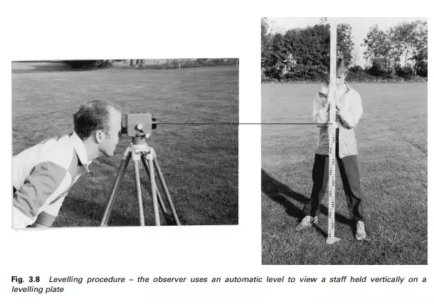
The equipment used in the levelling process comprises optical levels and graduated staffs. Basically, the optical level consists of a telescope fitted with a spirit bubble or automatic compensator to ensure long horizontal sights onto the vertically held graduated staff (Figure 3.8).
Levelling staff
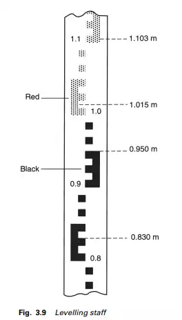
Levelling staffs are made of wood, metal or glass fibre and graduated in metres and centimetres. The alternate metre lengths are usually shown in black and red on a white background. The majority of staffs are telescopic or socketed in three or four sections for easy carrying. Although the graduations can take various forms, the type adopted in the UK is the British Standard (BS 4484) E-pattern type as shown in Figure 3.9. The smallest graduation on the staff is 0.01 m and readings are estimated to the nearest millimetre. As the staff must be held vertical during observation it should be fitted with a circular bubble.
Optical levels
The types of level found in general use are the tilting, the automatic level, and digital levels.
(1) Tilting level
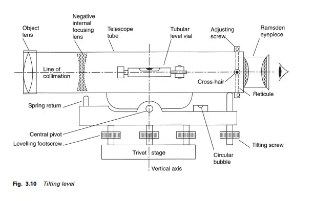
Figure 3.10 shows the telescope of the tilting level pivoted at the centre of the tribrach; an attachment plate with three foot screws. The foot screws are used to centre the circular bubble, thereby setting the telescope approximately in a horizontal plane. After the telescope has been focused on the staff, the line of sight is set more precisely to the horizontal using the highly sensitive tubular bubble and the tilting screw that raises or lowers one end of the telescope.
The double concave internal focusing lens is moved along the telescope tube by its focusing screw until the image of the staff is brought into focus on the cross-hairs. The Ramsden eyepiece, with a magnification of about 35 diameters, is then used to view the image in the plane of the cross-hairs.
The cross-hairs which are etched onto a circle of fine glass plate called a reticule must be brought into sharp focus by the eyepiece focusing screw prior to commencing observations. This process is necessary to remove any cross-hair parallax caused by the image of the staff being brought to a focus in front of or behind the cross-hair. The presence of parallax can be checked by moving the head from side to side or up and down when looking through the telescope. If the image of the staff does not coincide with the cross-hair, movement of the observer’s head will cause the cross-hair to move relative to the staff image. The adjusting procedure is therefore:
(1) Using the eyepiece focusing screw, bring the cross-hair into very sharp focus against a light background such as a sheet of blank paper held in front of the object lens.
(2) Now focus on the staff using the main focusing screw until a sharp image is obtained without losing the clear image of the cross-hair.
(3) Check by moving your head from side to side several times. Repeat the whole process if necessary.
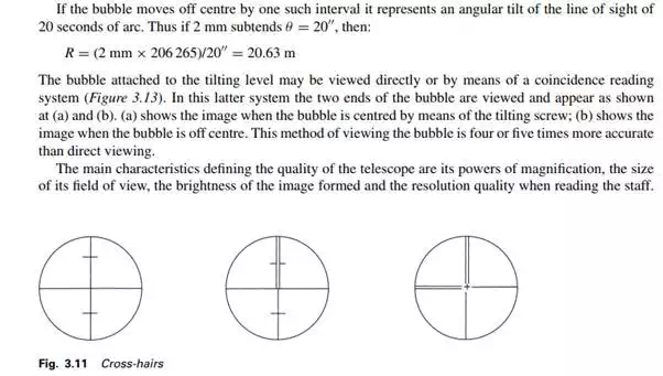
Different types of cross-hair are shown in Figure 3.11. A line from the centre of the cross-hair and passing through the centre of the object lens is the line of sight or line of collimation of the telescope.
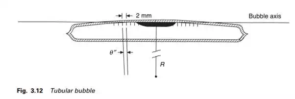
The sensitivity of the tubular spirit bubble is determined by its radius of curvature (R) (Figure 3.12); the larger the radius, the more sensitive the bubble. It is filled with sufficient synthetic alcohol to leave a small air bubble in the tube. The tube is graduated generally in intervals of 2 mm
All these are a function of the lens systems used and vary accordingly from low-order builders’ levels to very precise geodetic levels.
Magnification is the ratio of the size of the object viewed through the telescope to its apparent size when viewed by the naked eye. Surveying telescopes are limited in their magnification in order to retain their powers of resolution and field of view. Also, the greater the magnification, the greater the effect of heat shimmer, on-site vibration and air turbulence. Telescope magnification lies between 15 and 50 times.
The field of view is a function of the angle of the emerging rays from the eye through the telescope, and varies from 1◦ to 2◦. Image brightness is the ratio of the brightness of the image when viewed through the telescope to the brightness when viewed by the naked eye. It is argued that the lens system, including the reticule, of an internal focusing telescope loses about 40% of the light. The resolution quality or resolving power of the telescope is its ability to define detail and is independent of magnification. It is a function of the effective aperture of the object lens and the wavelength (λ) of light and is represented in angular units. It can be computed from P radians = 1.2λ/(effective aperture).
(2) Using a tilting level
(1) Set up the instrument on a firm, secure tripod base.
(2) Centralize the circular bubble using the footscrews or ball and socket arrangement.
(3) Eliminate parallax.
(4) Centre the vertical cross-hair on the levelling staff and clamp the telescope. Use the horizontal slow-motion screw if necessary to ensure exact alignment.
(5) Focus onto the staff.
(6) Carefully centre the tubular bubble using the tilting screw.
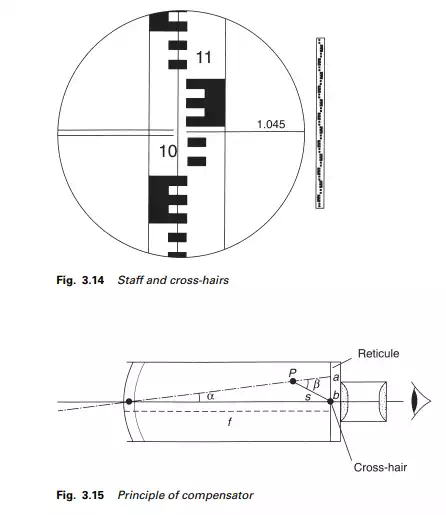
(7) With the staff in the field of view as shown in Figure 3.14 note the staff reading (1.045) and record it.
Operations (4) to (7) must be repeated for each new staff reading.
(3) Automatic levels
The automatic level is easily recognized by its clean, uncluttered appearance. It does not have a tilting screw or a tubular bubble as the telescope is rigidly fixed to the tribrach and the line of sight is made horizontal by a compensator inside the telescope.
The basic concept of the automatic level can be likened to a telescope rigidly fixed at right angles to a pendulum. Under the influence of gravity, the pendulum will swing into the vertical, as defined by a suspended plumb-bob and the telescope will move into a horizontal plane.
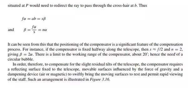
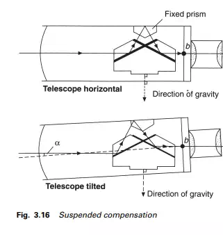
As the automatic level is only approximately levelled by means of its low-sensitivity circular bubble, the collimation axis of the instrument will be inclined to the horizontal by a small angle α (Figure 3.15) so the entering ray would strike the reticule at a with a displacement of ab equal to fα. The compensator
The advantages of the automatic level over the tilting level are:
(1) Much easier to use, as it gives an erect image of the staff.
(2) Rapid operation, giving greater productivity.
(3) No chance of reading the staff without setting the bubble central, as can occur with a tilting level.
(4) No bubble setting error.
A disadvantage is that it is difficult to use where there is vibration caused by wind, traffic or, say, piling operations on site, resulting in oscillation of the compensator. Improved damping systems have, however, greatly reduced this defect. During periods of vibration it may be possible to reduce the effect by lightly touching a tripod leg.
(4) Using an automatic level
The operations are identical to those for the tilting level with the omission of operation (6). Some automatic levels have a button, which when pressed moves the compensator to prevent it sticking. This should be done just prior to reading the staff, when the cross-hair will be seen to move. Another approach to ensure that the compensator is working is to move it slightly off level and note if the reading on the staff is unaltered, thereby proving the compensator is working.