What are Nodes and Elements in Finite Element Analysis?
Nodes and Elements are the very backbones of Finite Element Analysis. You will use them in every analysis you will perform in FEA, so learning about them seems like a good idea! So, what are Nodes and Elements in Finite Element Analysis?
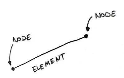
In FEA, you divide your model into small pieces. Those are called Finite Elements (FE). Those Elements connect all characteristic points (called Nodes) that lie on their circumference. This “connection” is a set of equations called shape functions.
Each FE has its own set of shape functions, that connect all of the Nodes of that Element). Adjacent Elements share common Nodes (the ones on the shared edge). This means that shape functions of all the Elements in the model are “tied” thanks to those common nodes.
Seems complicated? No worries – I will make it easy for you in just a second – just read on!
Finite Elements and their use
First of all, let’s deal with the Elements. In general, there are a lot of Finite Element types. But in such an overall post let’s just divide them into 1D elements (I will call beams), 2D elements (I will reference them as shells) and 3D elements (let’s call them solid).
The 1D element is just a line connecting two nodes.
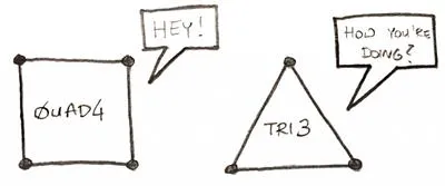
2D elements are usually triangular (TRI) and Quadrilateral (QUAD) in shape. This means that the most popular are:
3D solid elements can be based on triangles and quads as well, those will produce the epitome of Finite Elements – TET and HEX elements:
There are of course other types, like Wedges. Also, elements can be of higher order, which simply means they will have more nodes than those you can see above. But all in all, those are the “basic” types of elements. Since we have the “pictures” behind us, let’s go to the “shocking” news!
Elements do not exist!
This is always the “fun” part of explaining this. I know that when you mesh your model you can see the Elements on your screen. You know something like this:
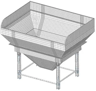
But, this doesn’t change a fact, that they aren’t real (in the most part). It’s easy to imagine that you cut your model into small pieces, and then do something with each piece separately. But this is not how the solver works. You see, the “real thing” are Nodes!
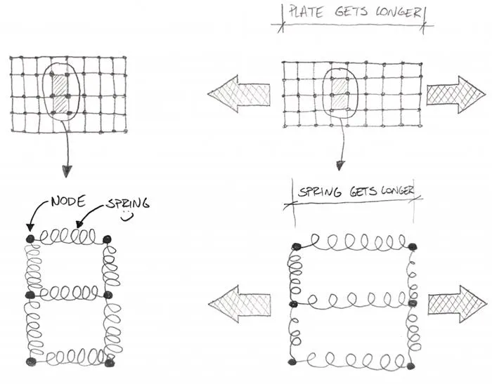
Did you notice that each element pictured in the previous part had a distinctive “dot” in each corner of its shape? That “dot” is a Node. Each “corner” of the Finite Element will have a Node! But as I mentioned before, some “higher order” Elements can actually have more Nodes that only the ones in the corners… this is irrelevant, however, in this explanation.
So picture this: instead of “chopping” your model into small pieces what you are actually doing is select important points (Nodes). Since “points” are only a set of coordinates you couldn’t really use them to calculate anything, could you?
This is why you want to connect those Nodes with “springs”. You know – if you put a plate under tension the Nodes in the plate will get further and further apart the more you pull right?
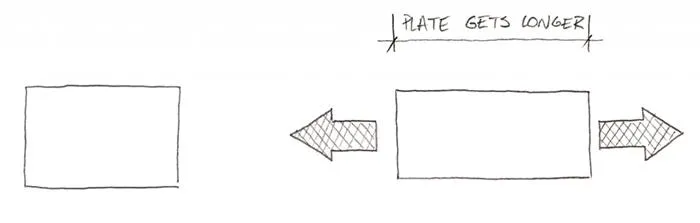
Of course, in the same plate under compression, the Nodes would get closer and closer. But it’s not for “free”. You need to apply a certain force to shorten or elongate the plate… because it resists the compression/tension.
So imagine we put several nodes at the plate, and then connect them with springs. Those springs will then elongate when pulled, and shorten when pressed… just like a “real plate”!
Looks reasonable right?
The art of the spring
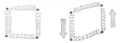
It would be great if you could just connect the nodes in an orthogonal network like that, but we all know it’s a bit more complicated right? The simplest question would be: “what about shear?”. Clearly, the plate resists shear, while our “spring set” doesn’t. Simply put it will behave like this, and since neither spring got longer or shorter, there was no resistance:
Let’s add diagonal springs as well in this case. This will make our “spring system” behave a bit better:
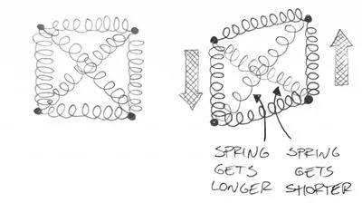
As you can see, when the shear deformation happens, the diagonal springs get longer/shorter. You need to use “force” to elongate/shorten a spring, so our model “resists” the shear deformation this way. To be completely honest, it’s even a bit more complicated than that, but I would say that the spring simplification is a neat one. Even if this is not perfectly correct, it’s a great way to visualize how it works!
So the question is: what does it means, that springs are connecting the Nodes? Well, let’s use a very simplified explanation (as always!). This basically means that there is an equation, that tells you how much Nodes on the ends of the spring move in relation to each other when you apply a force. You can derive the spring properties from material properties, plate thickness etc. In other words, this is “mathematically doable”.
Of course, everything depends on everything else, right? Imagine such a system:
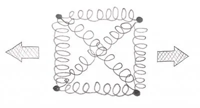
Horizontal springs carry the horizontal force of course, but diagonals do that as well! This means that those “spring equations” governing the relative movement of nodes against each other are “coupled”. Also, note that when diagonal springs get longer they also “produce” a resultant that will shorten the vertical springs of our system.