SEISMIC EVALUATION AND RETROFITTING OF BUILDINGS AND STRUCTURES
Concrete has been the most preferred construction material of the twentieth century, and unless a new material with spectacular characteristics is invented, it appears poised to remain this way for another century. This is not to suggest that there has been no progress on concrete and concrete technology over the years. Over the last 50 years, the strengths of various types of concrete have increased from the low levels of 15-20 MPa to values in the range of 40-70 MPa. Strength-based designs are slowly giving way to performance-based designs where strength is only one of the criteria to be satisfied. There is an increased attention being paid to life prediction and maintenance scheduling. Finite element software is extensively used in design offices for the analysis and design of concrete structures. It may be worthwhile at this stage to exactly calibrate the status of present day analysis and design viz., the “realistic estimates” on load effects and deformations. Consider, for example, the design of a multi-storeyed framed structure. The load cases to be considered are the dead load, live load, wind load, seismic load, and their combinations. The input data that is normally fed into the computer software includes modulus of elasticity, Poisson’s ratio, density of concrete, areas and moments of inertia of all structural elements, basic wind speed, zoning factor for seismic loading, and so on. Then one goes on to define the load combinations to obtain the worst load effects. Generally the gross section properties are used, and elastic
analysis is performed. The design is based on the limit state philosophy. So the elastic load effects that are obtained are multiplied by the load factors to obtain the capacity requirements. Theory of plasticity is then used to proportion the cross-sections for moments and axial forces. Linear variation of strain is assumed across the cross-sections, equilibrium equations for axial forces and moments are written down, and area of the steel reinforcement required is computed. What is done for the design for shear? This is more or less based on the empirical equations derived from the test results. The contribution of concrete is derived based on the strength of concrete and percentage of the tensile reinforcement. The contribution due to the web-steel is based on a 450 crack, though everyone realizes that the shear cracks seldom occur at this angle, depend on the M /Vd ratio, and even show change with the loading. The design is then claimed to be based on the limit state design philosophy covering limit states of serviceability and collapse. The limit state of serviceability is deemed to be satisfied if all the recommendations given in IS:456-2000 (BIS, 2000) regarding the detailing are satisfied.
Presently earthquake-resistant design is being discussed in many forums. If one adopts the provisions of IS:13920-1993 (BIS, 1993), the response reduction factor is 5.0 and for normal frames it is 3.0. This has direct impact on the design forces. The method of analysis and design as described above is the most sophisticated procedure adopted in the design offices. This is the present status, irrespective of what the inconsistencies are in elastic analysis, plastic design for moments and axial forces, and empirical approach for design for shear, bond, etc. It is extremely important to realize that the values obtained in the analysis are at best good indicators for the express purpose of “design”. The most essential part, and often the neglected part, is the proper guidance to aid engineers in making the best use of the results available and in providing the reinforcement adequately. It must be realized at this stage that when one attempts to carry out the seismic evaluation of a building, strictly speaking, the codal provisions at the time of construction, age of the structure, construction practices etc., all become important.
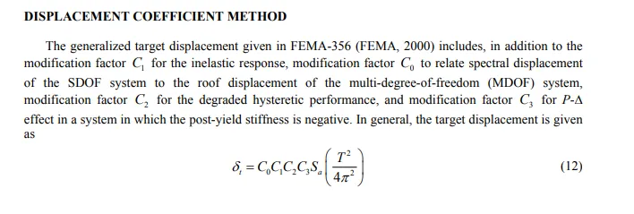
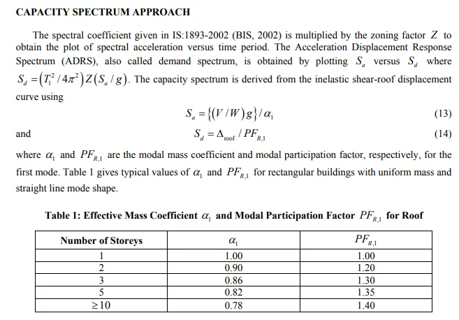
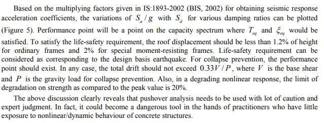
It must also be realized that if one is waiting for an exact methodology and rules for the seismic evaluation, one may have to wait for a few more years, if not decades. Presently, there are two nonlinear static analysis procedures available, one termed as the Displacement Coefficient Method (DCM) included in the FEMA-356 document (FEMA, 2000), and the other termed as the Capacity Spectrum Method (CSM) included in the ATC-40 document (ATC, 1996). Both of these methods depend on the lateral load-deformation variation obtained by using the nonlinear static analysis under the gravity loading and idealized lateral loading due to the seismic action. This analysis is generally called as the pushover analysis.


