SEISMIC RESPONSE CONTROL SYSTEM FOR NUCLEAR REACTOR BUILDING
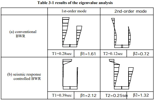
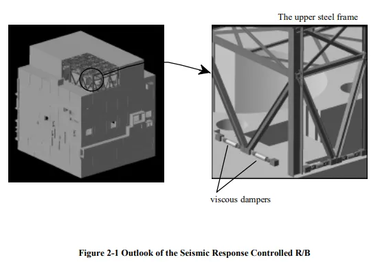
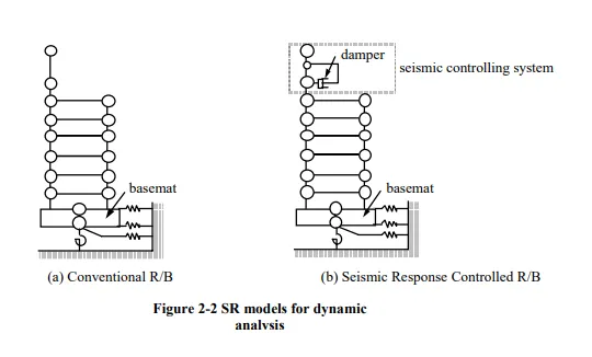
The conventional nuclear R/B is primarily made of a reinforced concrete (RC) structure. The shape of this structure is almost cubic and the length of each side is approximately 60m, as shown in Figure 1-1. The total weight of this building is more than 200,000 tons. The foundation mat is directly set on a support rock ground. The building’s structure has a reinforced concrete containment vessel (RCCV) and box wall surrounding the RCCV. These shear walls are interconnected through the floor slabs. Therefore, the overall building is a structure with high degree of rigidity. As shown in Figure 2-2(a), the sway/rocking (SR) model (two-cantilever model of the bending shear-type building) is adopted for the dynamic analysis model. The base spring constant is derived using the vibration admittance theory, where Novak’s theoretical solution is used to derive the side-surface spring constant. Because the conventional R/B is primarily made of reinforced concrete from top to toe, the natural period is relatively short (the first-order natural period T1=0.28sec) and the natural vibration mode is drawn in a smooth curve, as shown in the upper frame of Table 3-1. Conventional seismic response control systems, such as tuned mass damper, are not considered feasible because the tuned mass needed in such a case would be too heavy. “A seismic response control building with soft upper steel frame”, referred to as ‘the (seismically) controlled R/B’, has been developed for boiling water reactor (BWR) buildings. The outlook of the structure is shown on Figure 2-1. The upper steel frame story, positioned above the crane level of the building, was designed much less stiff than the RC structure below the crane level. The weight of the roof and the steel frame works as a kind of “tuned mass” for a conventional seismic response control building. The weight occupies approximately 2% of the total weight, which is heavy enough to control the whole building. A couple of viscous dampers were installed in each span of the steel frame for the purpose of preventing excessive acceleration of the steel frames. The dynamic analysis model for the seismically controlled R/B is shown on Figure 2-2(b). The vibration characteristics of “the controlling structure”, called the upper steel frame, can be defined by the stiffness of the steel frame, K, and the damping coefficient, C.
MECHANISMS OF SEISMIC RESPONSE REDUCTION
The mechanisms of seismic response reduction of the seismic response control building with soft upper steel frame can be explained by the eigenvalue analyses results, shown in Table 3-1. The first-order natural vibration mode of the conventional R/B, which is shown on the upper frame in Table 3-1, is the principal vibration mode with a high participation factor, β, where the deformation simply increase from bottom to the top. On the other hand, the seismically controlled R/B has two principal modes, the first-order and the second-order mode. In the first-order natural vibration mode of the controlled R/B, which is shown on the lower frame in Table 3-1, the deformation is concentrated at the upper frame, and little deformation can be observed in lower RC structure. The second-order natural vibration mode of the controlled R/B corresponds to the first-order mode of the conventional R/B. In this mode, the deformation of the lower RC structure increases from the bottom to the top, but the upper structure deforms in the opposite direction from the lower structure as if the upper structure controls the deformation of the lower structure. As a result of the contribution by this mode, the seismic responses of whole building, such as the overturning moment of the building and/or the shear stress in the shear walls, are expected to be reduced. Furthermore, by installing the dampers in each span of the steel frames, the energy consumption by these dampers can also contribute the response reduction in the dynamic analyses.