Buckling length in sway and non-sway structures
One of the few difficult things about buckling lengths is, that you need to know if your structure is a “sway” structure or a “non-sway” structure. Commonly the simple check is made with displacements, but unfortunately, it may lead to serious mistakes!
Why should you care about sway and non-sway system
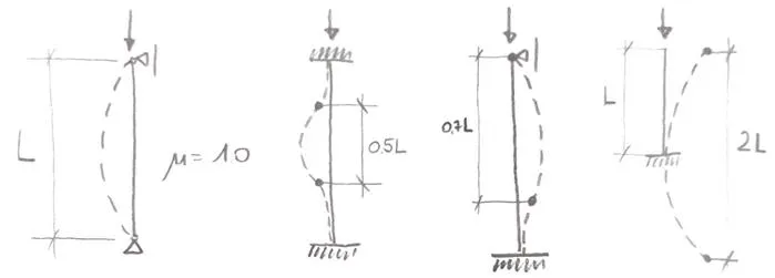
Firstly, I want to show you why “type” of a system is crucial in buckling design. In the previous post about buckling length, I have shown a chart that is very popular. It is often used in textbooks when buckling length is described:
This set only works in non-sway structures, and is it so easy to forget that! To make it simple if you have a frame like this, everything is fine:
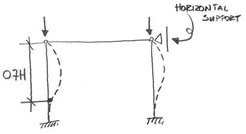
Unfortunately, when you remove the horizontal support from the top, problems start to happen. The column is still rigidly connected at the bottom, with a hinge at the top. This suggests that the buckling length coefficient should be 0.7 as in the picture above. But the top connection is made to… nothing really. The entire top (with the beam) will move in horizontal direction! This will result is a deformation like this:
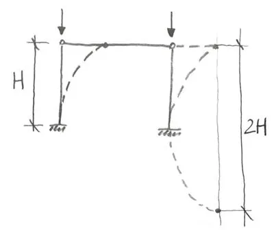
Even though the type of the connection did not change (it is still rigid at one side and hinge at the other) the buckling length did! And the change is huge from 0.7H to 2H.
This is the reason why you want to be certain what type of structure you are dealing with!
Bracings to the rescue!
The “sway” and “non-sway” problem is one of the reasons why we like to use bracings in our structures. A simple “X” bracing will prohibit the movement of the top part, meaning that we will have a “non-sway” system. But is it always so?
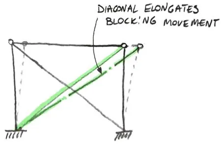
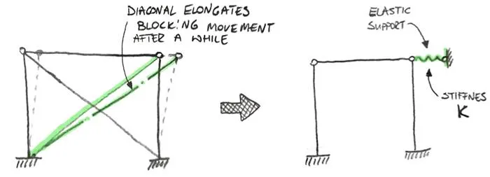
Let’s think a second about what bracings really do. In a “typical X” bracing one part of the bracing elongates under tension (while other part buckles under compression). This elongation of the bracing part means, that a normal force appears in the rod. The more we try to “sway” our structure, the longer the part in tension must become. This also means that the normal force will be higher and higher. Hence, our bracing rod “fight” against this horizontal movement:
However, to block the movement a certain force in the rod must be generated. This means that the bracing is effective but after a while. Furthermore, the smaller the cross-section of the bracing, the more horizontal movement will be possible.
At this stage, I have to ask: where is the “allowable” limit of this translation before the frame is a “sway” frame anyway? Whenever I approach a problem it is hard to solve I try to imagine 2 extremes.
Whenever I approach a problem it is hard to solve I try to imagine 2 extremes. In this case, the diameter of the rod can be 100mm (one extreme). In such a case there will be no movement at all and a structure is clearly a “non-sway” structure. On another extreme, the rod can be 0.1mm in diameter. Before it will elongate enough to carry any substantial force the structure will collapse. In such a case it is clearly a “sway” structure.
We can think about it in a simplified way: a bracing is nothing more than an elastic support at the top of the frame:
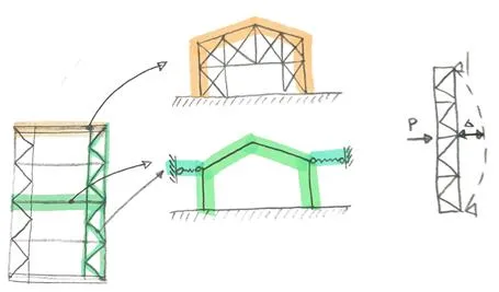
Of course, such a bracing is not the only way to get an elastic support at the top. You can for instance also think about a short hall building with very rigid end walls and horizontal longitudinal trusses along the roof. Then those trusses support the horizontal movement of each truss in an elastic manner. This is shown in a simplified way below:
It’s time to ask: How to check if my structure is a “sway” structure. Unfortunately, this is not an easy question.
Classical way of checking if you have a “sway” structure
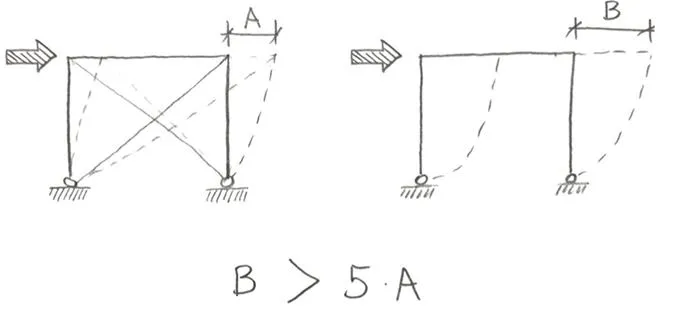
In a lot of books, a “classical” method of checking if you have a “sway” structure is described. According to this method, all you have to do is to check the deformations of the structure with and without the bracings. Then you compare those deformations. If structure without the bracings deforms 5 times more than the one with the bracings, this is a “non-sway” structure.
The reasoning behind this method is simple. If the deformations with the bracings are much smaller, then the bracings are “effective”. If so, we can assume that the top won’t move, and the structure won’t “sway”.
But as always with such methods, a reasonable question should be asked… why 5 times? Why not 10 or 2 times? And in the end, is the 5 times a correct value?
Unfortunately, it seems that it isn’t, and I will show it to you with our frame as an example.
To sway, or not to sway – that is the question!
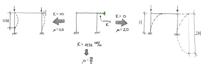
Let’s take a look at what we know so far. You already know that we can treat bracings as an elastic support with stiffness K. Also if there are no bracings (K=0) the buckling coefficient in our case is 2.0. On another side, if the bracings are indestructible (K = infinity) the buckling coefficient is 0.7. What we don’t know is, what happens between those two states. It is easy to show this on a simple drawing:
Luckily for us, LBA can provide us with all the answers that we need. I will simply make a model of such frame, and I will check the critical load multiplier for different stiffness of this elastic support. This way we can draw conclusions about how bracing stiffness influence buckling length of the columns!
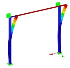
To do the check I have created a model that would resemble a wall bracing in a hall building. The columns are from I sections (but with “strong axis” in the other direction. The horizontal element is a round pipe (acting as a part of a bracing system). I ignored implementing roof rafters etc. I simply assumed that they are correct, and I have made a support in “Y” direction at the top. There is also an elastic support in the top right corner of the frame in “X” direction:
It’s high time to do the analysis!
Sway me more…
First, two states are “easy”. Firstly I did an analysis without this elastic support (K = 0 kN/m). Horizontal deformation from a test load I applied was 38mm. Critical load multiplier was 0.3.
Second “easy” case was with the infinitely rigid “X” support. In such case, horizontal deflection is of course 0mm. Critical load multiplier is 1.68.
Of course, I also did some intermediate results. You can see some of them below:
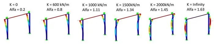
With several outcomes, I did some charts, showing how things change. As a reference point, I used the ratio of horizontal displacement between unbraced system and system with bracings (B/A from one of the pictures above). In such scale 5 means that it is a non-sway system according to the classical approach.
As you can see critical force changes “fluidly” between a sway system (that would be 1 on the horizontal axis) and the non-sway system (theoretically a 5, basically on the right side of the chart). Changes in critical buckling force of course mean, that buckling length coefficient is changing as well, and this change can be seen below:
However both of the values may seem a bit “abstract”, so I made a simple example and below you can see how capacity ratio changes. This is for the purely compressed column in my frame, and in different systems, this will be different of course. But at least it is a good reference point:
There are no outcomes for elements with deformation ratio smaller than 5. The compressive force was then higher than critical buckling load and it is non-designable. Also, note that the vertical axis starts from 0.8, not from 0.