Determining The Transferred Maximum In-Plane Diaphragm Shear Forces To Walls
Let’s extend the application of Mohr’s circle to a topic very dear to us structural engineers dealing with lateral loads, seismic loads especially, that is being transferred from the structural diaphragm to the resisting core and shear walls.
Say for some reason you’d want to know the shear at the interface of the slab and the wall because of the in-plane shear transfer from the slab, to the reinforcement and eventually into the wall. Obviously, it will be a mixture of forces acting at a variety of orientations, so there is no such thing as pure shear perfectly acting in parallel to the wall. Nonetheless, we need to know the shear just so we can satisfy our random urges for (in)sanity checks and for some other purposes.
So how do you do this? I prepared a sample calc for you below (you can download the calculations by clicking here). While this was done using ETABS, I believe other software also have this capability of showing the principal in-plane diaphragm forces. That, I leave to you to figure out how.
Let’s proceed.
Figure 1 below shows the part plan of the shearwall and its orientation on the global X and Y axes.
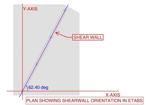 Figure 1. By yours truly
Figure 2 shows the shell forces shown as arrows. In ETABS, all you have to do is show the “Shell Forces/Stresses” dialogue box (press F9 if you’re using version 17), select the FMax component, tick “Show Fmax/Fmin as Arrows” and click either “Apply” or “Ok”. Note that these are the maximum and minimum principal stresses/forces to which our pal Christian Otto Mohr, graphically represented them as the extreme west and east points of a circle where the ordinate is zero. Or simply, the points in circle with zero shear. Since the principal stresses vary along the length of the shearwall, I just took the maximum, hence the most conservative value.
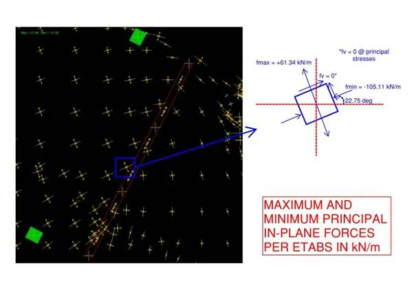 Figure 2. By yours truly
In Figure 3, I hypothesized that the maximum shear will align exactly to the orientation of the wall, but it ended a bit off eventually, 5 degrees to be exact based on Figure 4. To get the maximum value of shear, it should be the point in the circle with the highest ordinate. So we only need to work out the radius of our circle and poof we now have the maximum shear transferred to the wall of 83.225 kN/m acting at 67.75 degrees counterclockwise from the horizontal. We can actually get the shear parallel to the wall by working out the geometry of the Mohr’s circle but it will only be a bit lower than 83.225 kN/m. Considering our wall having a length of 6.230 m, the total shear transferred in-plane to the wall on the west side is roughly (I put emphasis on the word roughly) 83.225*6.23 = 518.50 kN.
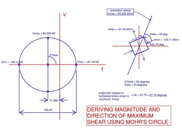 Figure 3. By yours truly
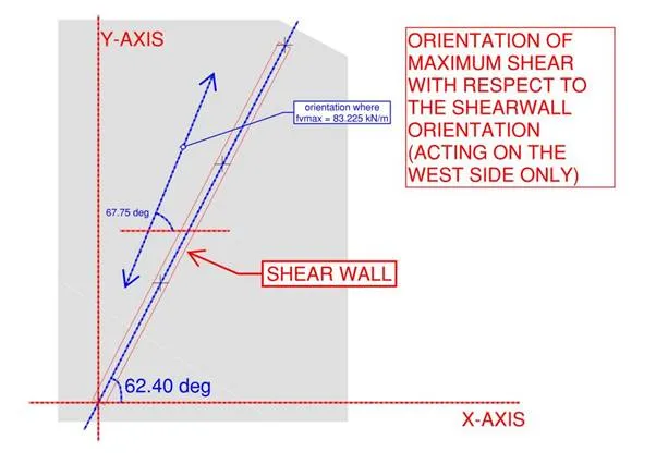 Figure
4. By yours truly
Figure
4. By yours truly
All good?
Now before you get too excited thinking that the shear transferred here constitutes all the shear forces going to the wall then I advise you to please hold your horses and consider the following while looking at Figure 5 below showing the flow of the diaphragm in-plane forces:
Forces come from both east and west sides of the wall
The south part of the wall also experiences a push from the same diaphragm
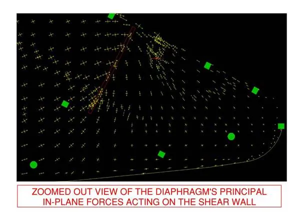 Figure 5. By yours truly
So the total shear transferred to the wall isn’t just coming on one side based on our sample calculations above. And again, this example doesn’t cover all possible scenarios that we can possibly imagine so the bottom line is to have a closer look and assess the whole picture instead of just focusing on several separate scenarios.