Setting Correct Expectations On Lfrs Involving Transfers
Gravity dictates that what’s up must go down. The same can be said of lateral loads be it seismic or wind: summation of applied lateral load equals the lateral base reactions.
In order for the two statements to become true, gravity and lateral loads must follow a load path towards their final destination. And things like how the hell did some forces here disappear and magically appeared somewhere else is our main objective to determine and understand.
For gravity loads, ideally, the load from above should follow a single linear concentric path going down. For lateral loads, ideally, the shear that the wall carries should have some vertical concentric path to the foundation below. But if that’s not the case, the load gets carried and transferred elsewhere hence the term discontinuity.
And the efficiency of the discontinuous load path which is a detour from what is usually intended is what overstrength requirement is all about.
I thought it was that easy but dang was I wrong. Turns out, it’s more than just multiplying the seismic loads with 2.8 or any Ω-factor for that matter. What is dang hard is to pinpoint how the load transfers along that discontinuity which is complex and not very straight forward despite the advancement of structural analysis programs such as ETABS.
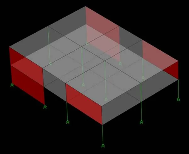
Is it really that hard you say? Maybe it’s just me but you be the judge. For now let’s look at a rather simple model and trace how the lateral load made it’s way down to the foundation even with the discontinuity. Only seismic lateral load (no eccentricities) on the building’s strong axis is applied for simplicity and analyzed such that both edges with walls and transfer columns have equal take on the story shear.
 by yours truly
In the figure above, what connects the continuous and discontinuous walls is a slab with no beams.
 by yours truly
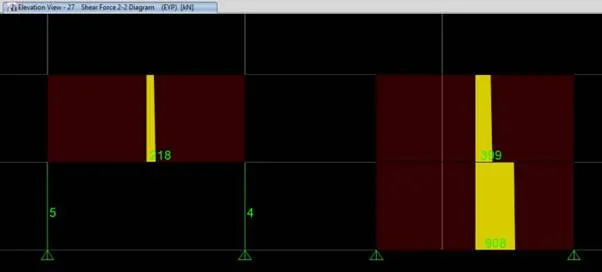
The figure shows the shear diagrams of the frame and wall element. Total base shear computed is 1840kN. Taking a half of which, we get 920kN. At the level of the wall on top of 2 transfer columns, the said wall takes it’s share of the seismic story shear. Below it where there were transfer columns, they can no longer take a significant share of the story shear because the columns will never be as stiff as the wall above (hence the term discontinuity). And it’s supposedly share of the story shear, as structural analysis dictates will be absorbed by other walls more capable of taking the extra shear. In this case, only the single wall at the bottom level takes the total shear on one panel (908 kN ≈ 920 kN).
But what is happening to the transfer columns?
 by yours truly
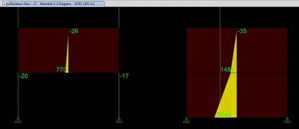
No significant bending moment is transferred to the transfer columns which proves the rule of stiffness.
 still by yours truly
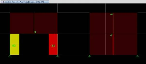
Axially, the bending moment from the discontinuous wall translated to a push-pull action on the transfer columns. The bars needed to resist the action of which should be properly detailed so that the continuity of bars going from the column to the wall and bars from the wall into the columns will be seamless.
Now my favorite part, the shear transfer. The 218 kN shear carried by the discontinuous wall cannot and did not transfer to the columns. And how will this shear reach it’s final destination if not in the columns?
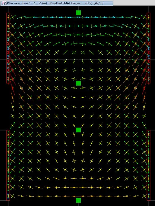
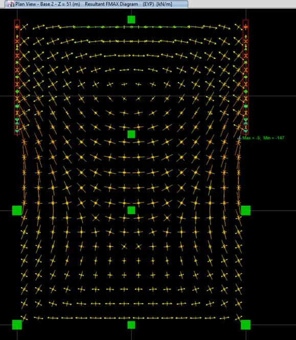
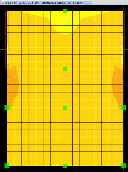
In this particular example, the slab bridging the two walls is going to take over (in which, when translated to an actual project should be adequate to carry the forces resulting from the discontinuity) by means of compression-tension action. The principal forces are shown at topmost and next level, respectively. Notice that the tributary width transferring shear forces via compression from one wall to the other varies and cannot be readily determined. Finally, we have the F22 contour which is parallel to the global Y axis showing the concentration of compressive forces on the slab in between the walls.
Is this some sort of unnecessary overthinking? It’s both yes and no but the thing is we need to have it covered if we want a robust design.
And if you still think this topic is very straight forward and can be readily identified without thorough analysis, then just like myself previously you’re dead wrong. Remember that what I presented is but a simple example compared to the projects we have encountered or will still be encountering in the future.
Now going back to the code provision for overstrength, where are we going to apply the Ω-factor?
For argument’s sake I will apply the Ω-factor to the transfer columns to account for the push-pull action. In that way, I can account for the possible surge of tension compression forces in the columns. Bending-wise? I don’t think it would affect the flexural capacity of the columns even if we increase the overstrength factor to 5.
Other mind-boggling questions would be:
For shear, am I going to bring down the shear from the discontinuous walls to the columns pursuant to 1630.8.2.1 of UBC97 and 12.3.3.3 of ASCE 7-10?
For the slab carrying the shear forces via compression, how am I going to detail it let alone analyze the load path?
Should the exception 1 of 1630.8.2.1 of UBC97 have a continuation of “… And Em should not be less than the force that is transferred to the element by the lateral force resisting system.”