The Direct Stiffness Method: Beams
Instructional Objectives After reading this chapter the student will be able to
1. Derive member stiffness matrix of a beam element.
2. Assemble member stiffness matrices to obtain the global stiffness matrix for a beam.
3. Write down global load vector for the beam problem.
4. Write the global load-displacement relation for the beam.
Introduction.
a few problems were solved using stiffness method from fundamentals. The procedure adopted therein is not suitable for computer implementation. In fact the load displacement relation for the entire structure was derived from fundamentals. This procedure runs into trouble when the structure is large and complex. However this can be much simplified provided we follow the procedure adopted for trusses. In the case of truss, the stiffness matrix of the entire truss was obtained by assembling the member stiffness matrices of individual members. In a similar way, one could obtain the global stiffness matrix of a continuous beam from assembling member stiffness matrix of individual beam elements. Towards this end, we break the given beam into a number of beam elements. The stiffness matrix of each individual beam element can be written very easily. For example, consider a continuous beam as shown in Fig. 27.1a. The given continuous beam is divided into three beam elements as shown in Fig. 27.1b. It is noticed that, in this case, nodes are located at the supports. Thus each span is treated as an individual beam. However sometimes it is required to consider a node between support points. This is done whenever the cross sectional area changes suddenly or if it is required to calculate vertical or rotational displacements at an intermediate point. Such a division is shown in Fig. 27.1c. If the axial deformations are neglected then each node of the beam will have two degrees of freedom: a vertical displacement (corresponding to shear) and a rotation (corresponding to bending moment). In Fig. 27.1b, numbers enclosed in a circle represents beam numbers. The beam is divided into three beam members. Hence, there are four nodes and eight degrees of freedom. The possible displacement degrees of freedom of the beam are also shown in the figure. Let us use lower numbers to denote unknown degrees of freedom (unconstrained degrees of freedom) and higher numbers to denote known (constrained) degrees of freedom. Such a method of identification is adopted in this course for the ease of imposing boundary conditions directly on the structure stiffness matrix. However, one could number sequentially as shown in Fig. 27.1d. This is preferred while solving the problem on a computer.

![]()

![]()


![]()
In the above figures, single headed arrows are used to indicate translational and double headed arrows are used to indicate rotational degrees of freedom.
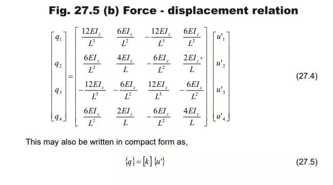
Beam Stiffness Matrix.
a prismatic beam of a constant cross section that is fully


![]()



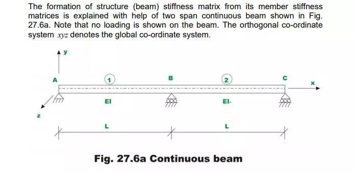
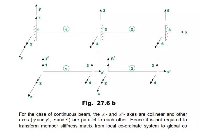
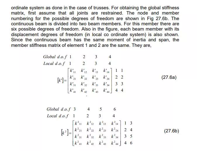
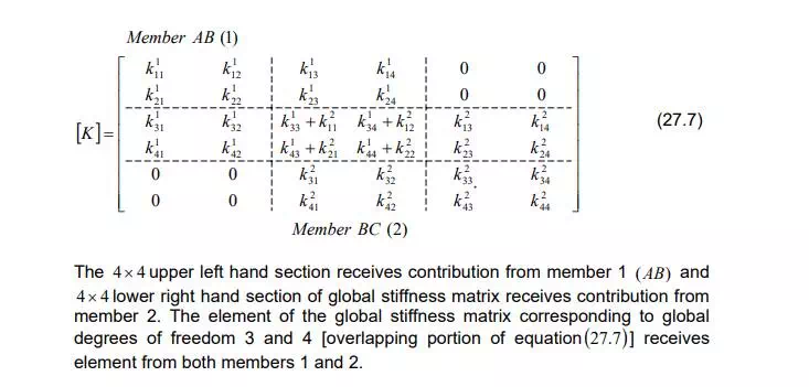
Beam (global) Stiffness Matrix.

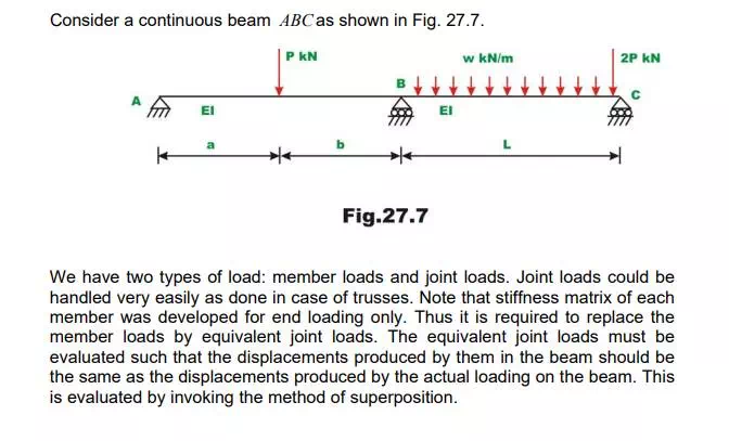
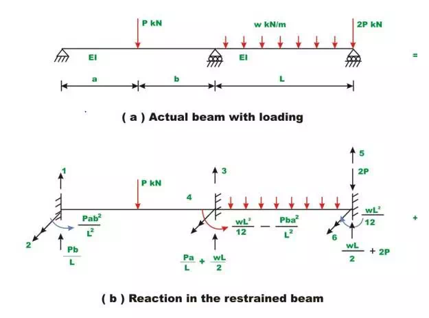
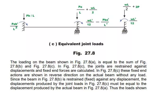
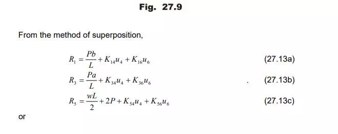
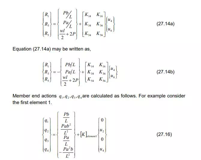
Formation of load vector.
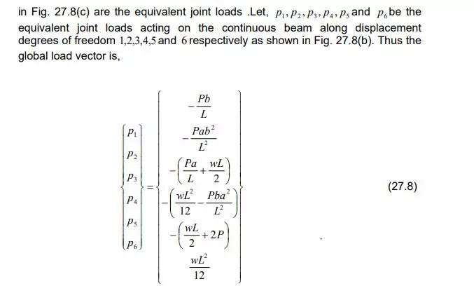
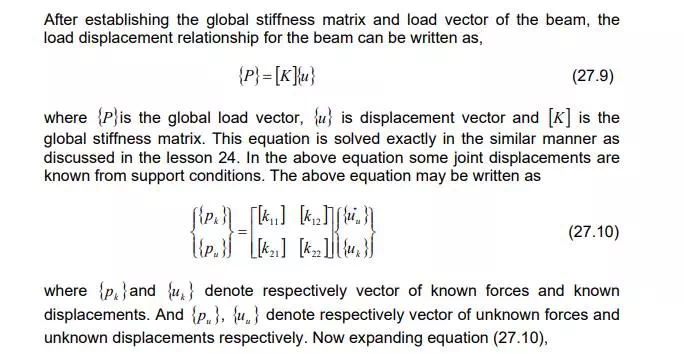
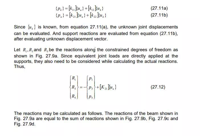
Solution of equilibrium equations
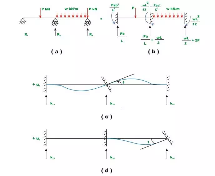
In the next lesson few problems are solved to illustrate the method so far discussed