Modelling of Arch Structures
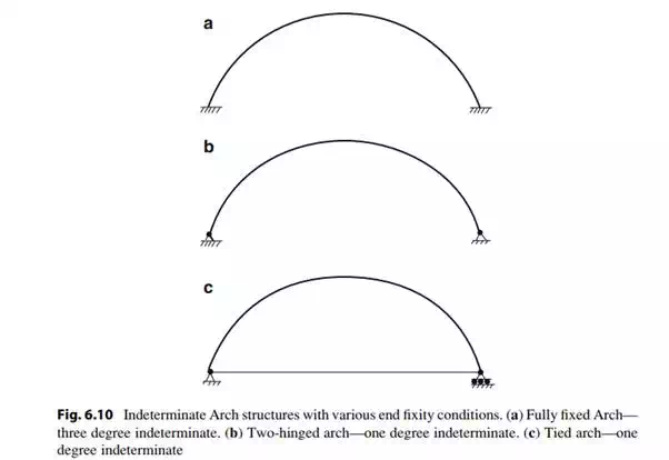
We idealize an arch structure as a curved member restrained at its ends with a combination of fixed, hinged, and roller supports. Figure 6.10 illustrates various types of end conditions. Case (a) corresponds to full end fixity, a condition that is difficult to achieve. The more common case is (b) where the abutments can prevent translation but not rotation. We refer to this structure as a two-hinged arch. The third case, (c), corresponds to a “tied arch structure” where the ends are interconnected with a tension member. This scheme is used when the abutments are not capable of resisting the horizontal thrust action of the arch.
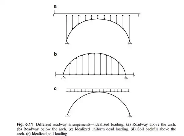
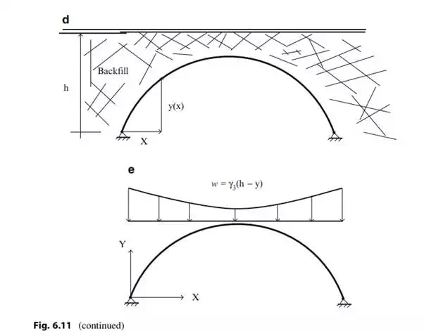
If the arch is a bridge, the roadway may be connected above the structure as in Fig. 6.11a, or below the structure as in Fig. 6.11b. When placed above, the deck weight is transmitted by compression members to the arch. Decks placed below the arch are supported by cables. Both loading cases are idealized as a uniform loading per horizontal projection as shown in Fig. 6.11c. In some cases, soil backfill is placed between the roadway and the arch. The soil loading is represented as a non-uniform loading whose shape is defined by the arch geometry. Figure 6.11d, e illustrate this case.
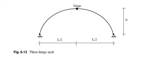
The structures in Fig. 6.10 are statically indeterminate. We can reduce the two hinge arch to a statically determinate structure by converting it to a three-hinge arch. The additional hinge is usually placed at mid-span as shown in Fig. 6.12.


In this chapter, we first present a general theory of statically determinate curved members and then specialize the general theory for three-hinge arches.