Statically Determinate Curved Members
Overview
Beams are straight members subjected to transverse loading. We showed there that transversely loaded beams respond by bending, i.e., they equilibrate the loading by developing internal shear and moment quantities. When the centroidal axis is curved, the behavior of a curved member subjected to transverse loading, depending on how the ends are restrained, can undergo a dramatic change from predominately bending action to predominately axial action. This characteristic of curved members makes them more efficient than straight members for spanning moderate to large scale openings. A typical application is an arch structure, which is composed of curved members restrained at their ends.
In this chapter, we first develop the general solution for the internal forces in a planar curved member and apply it to members having parabolic and circular shapes. Next, we introduce the method of virtual forces specialized for planar curved members and illustrate its application to compute displacements for various geometries. The last section of the chapter deals with the optimal shape for an arch and the analysis of three-hinged arches, a popular form of arch structure..
A Brief History of Arch-Type Structures
We define an arch as a curved member that spans an opening and is restrained against movement at its ends by abutments. Figure 6.1 illustrates this definition. Arches are designed to carry a vertical loading which, because of the curved nature of the member, is partially resisted by horizontal forces provided by the abutments. Arches generally are more efficient than straight beam-type structures for spanning an opening since their geometry can be modified so that they carry the transverse loading almost completely by axial action, i.e., by compression. However,
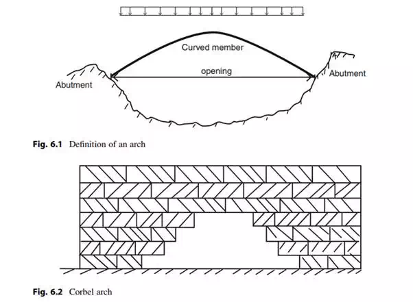
abutments are required to develop the compression type behavior and this requirement sometimes limits the applicability of the arch for a particular site.
In what follows, we briefly discuss the historical development of arch structures and then present the underlying theory for statically determinate curved members. This theory is similar to the theory for gable roof structures.
Arches have many applications. They are used for openings in walls, for crossing gorges and rivers, and as monumental structures such as the Arc de Triumph. The first application of arch-type construction in buildings occurred around 4,000BC in Egypt and Greece. Openingsin walls were spanned usingthe scheme shown in Fig. 6.2. Large flat stones were stacked in layers of increasing width until they met at the top layer. Each layer was stabilized by the weight applied above the layer. The concept is called a Corbel arch. No formwork is required to construct the structure. Also, no horizontal thrust and therefore no abutments are needed. The term “false arch” is sometimes used to describe this type of structure. False arches were used almost exclusively in ancient Greece where the techniques of masonry construction were perfected.
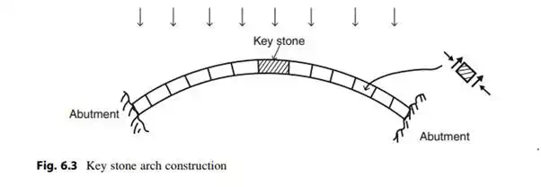
The type of arch construction shown in Fig. 6.3 for carrying vertical loading across an opening was introduced by the Egyptians around 3,000BC. It employs tapered stones, called voussouirs, which are arranged around a curved opening in such a manner that each brick is restrained by compressive and frictional forces. The system is unstable until the last stone, called the “keystone,” is placed. Consequently, temporary framework is required during construction.
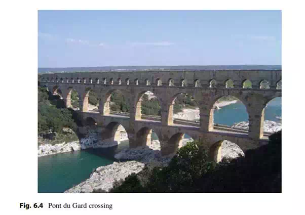
Starting around 300BC, the Romans perfected masonry arch construction and built some unique structures, many of which are still functioning after 2,000 years. They preferred circular arches and included them in buildings, bridges, and aqueducts. One of the most famous examples is the Pont du Gard, shown in Fig. 6.4; a bridge/aqueduct over the river Gard built in 19BC. Some of the stones weigh up to 6 t.
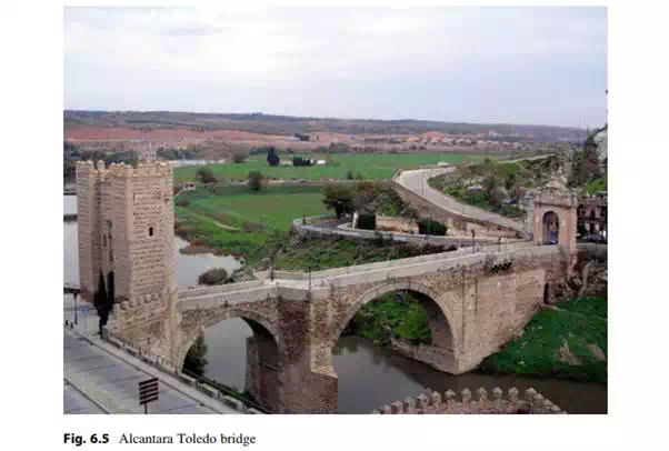
Another example of a second century multiple span Roman arch masonry bridge is shown in Fig. 6.5. The typical span length is 98 ft. This bridge crosses the Tagus River in Spain and was a key element in the transportation network connecting the outer Roman Provinces with Rome.
Masonry materials are ideal for arch construction since they are strong under compression and also very durable. However, it is difficult to construct long span masonry arch bridges. With the development of alternate structural materials such as cast iron and steel at the end of the eighteenth century, there was a shift toward arches formed with metal members. Figure 6.6 shows the Iron Bridge built in 1781.
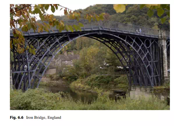
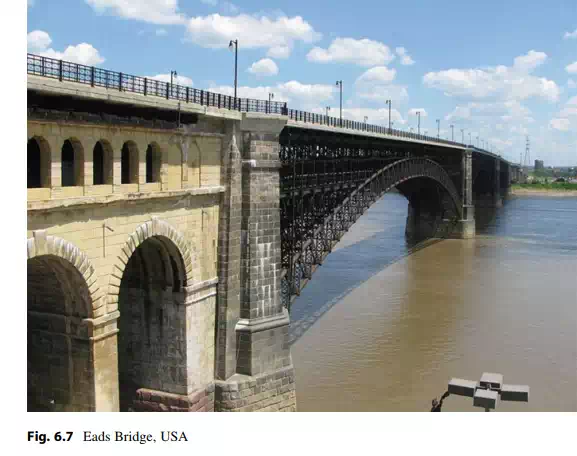
The main span is 100 ft and crosses the Severn Gorge in the UK. Each of the members was formed using cast iron technology which was evolving at the time. Since cast iron is weak in tension and tends to fail in a brittle manner, it was shortly replaced as the material of choice by steel. The development of railroads created a demand for bridges with more load capacity and longer spans. During this time period, there were many arch bridges constructed. Figure 6.7 shows the Eads Bridge built in 1874 across the Mississippi River in St. Louis, Missouri. This bridge has ribbed steel arch spans of 520 ft, fabricated with tubular structural alloy steel members; the first use of steel in a major bridge project. Today, the bridge is still carrying pedestrian, vehicular, and light rail traffic across the Mississippi.
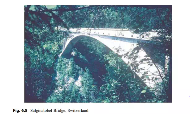
At the end of the nineteenth century, reinforced concrete emerged as a major competitor to steel as a structural material. Reinforced concrete allowed one to form arch geometries that were aesthetically more pleasing than conventional steel arch geometries, and therefore became the preferred material. Most of this surge in popularity was due to the work of Robert Maillart, a Swiss Engineer (1872–1940), who developed arch concepts that revolutionized the design practice for reinforced concrete arches. An example is the Salginatobel Bridge, shown in Fig. 6.8. This bridge, built in 1930, crosses the Salgina Valley Ravine in Switzerland with a span of 270 ft. It is the ideal solution for this picturesque site and has been recognized by ASCE as a landmark project.
A unique arch bridge in the USA is the New Gorge Steel Arch Bridge located in West Virginia. Opened in 1977, it has the longest main span (1,700 ft) and highest height (876 ft) of all arch bridges in North and South America. It held the world record for span and height until 2003 when the Lupu Arch Bridge in Shanghai (1,800 ft span) was opened. A type of weathering steel called Corten was used in the New Gorge Arch structure in order to avoid the need for periodic painting.
Another unique arch bridge in the USA is the Hoover Dam Bypass Bridge. Segmented concrete construction was used to fabricate the concrete box elements in situ. The construction process employed a complex tieback scheme, as illustrated in Fig. 6.9b–d. The bridge was completed in 2010.