Cables Subjected to Concentrated Loads
Horizontal Cables
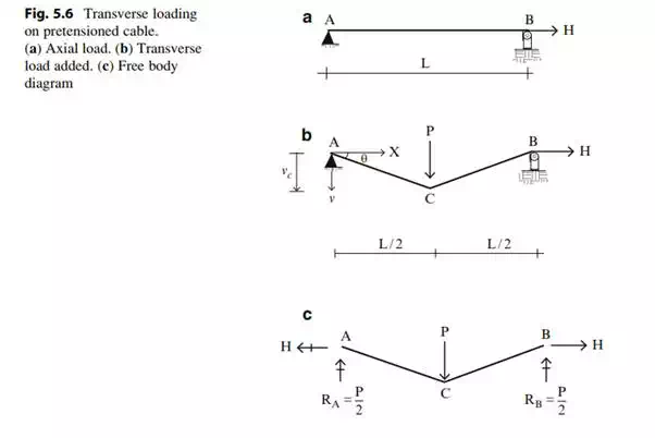
Suppose we conduct the following experiment shown in Fig. 5.6. We start with a horizontally aligned cable that is pin connected at A, supported with a roller support at B, and tensioned with a force H. We then apply a concentrated load, P, at mid-span. The cable adopts the triangular shape shown under the action of P. Two questions are of interest. Firstly, why a triangular shape? Secondly, how is the downward vertical displacement at mid-span related to P and H? Historically, the term “sag” is used to describe the vertical motion of a cable.
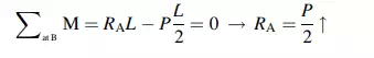
We answer these questions by noting that the magnitude of the moment at any section along the length of the cable must be zero since a cable has no resistance to bending. Summing moments about B
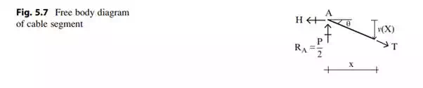
Next, we consider the
free body diagram for the arbitrary segment shown in Fig. 5.7. Setting the
moment at x equal to zero leads to an expression for the sag, ![]()
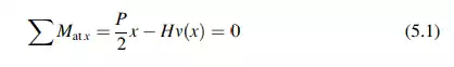
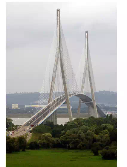
Fig. 5.4 Normandy Bridge, France
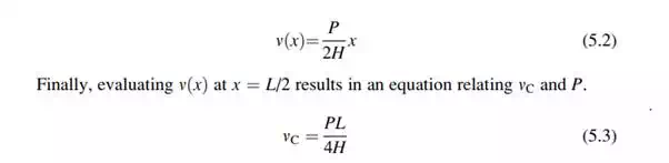
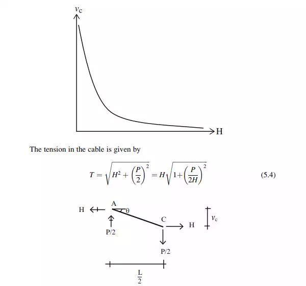
The relationship between
![]() and
H is plotted below. Usually, one specifies H and determines
and
H is plotted below. Usually, one specifies H and determines ![]() .
However, there are cases where one specifies
.
However, there are cases where one specifies ![]() , and determines the
required value of H. In general for cable systems, one needs to specify either
a force or a sag in order to define solution.
, and determines the
required value of H. In general for cable systems, one needs to specify either
a force or a sag in order to define solution.
![]()
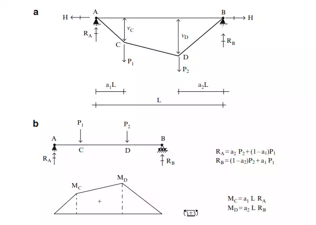
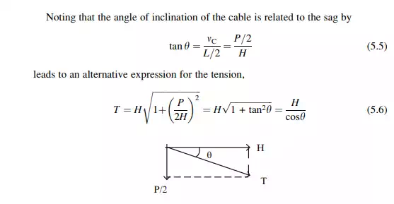
Equation (5.1) combines two moment distributions, one due to the transverse loading P and the other due to H. The moment due to P can be interpreted as the moment in a simply supported beam spanning between points A and B, the support points for the cable. Figure 5.8 shows this distribution.
We express (5.1) as
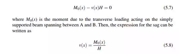
We interpret this result as follows. The shape of the vertical sag of the cable from the horizontal chord is a scaled version of the moment diagram for the transverse loading acting on a simply supported beam spanning between the cable supports.
We extend this reasoning
to a cable subjected to multiple concentrated loads. Figure 5.9a illustrates
this case. The moment diagram for a set of concentrated loads is piecewise
linear, with peak values at the points of application of the concentrated
loads. It follows from (5.8) that the shape of the cable is also piecewise
linear. Details are listed below. One generates ![]() , the corresponding
shear
, the corresponding
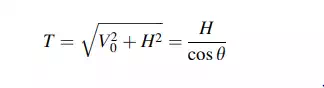
shear ![]() , the displacement n, and the
tension T. Note that one has to specify either H or one of the vertical
coordinates (nC or nD) in order to compute the shape
, the displacement n, and the
tension T. Note that one has to specify either H or one of the vertical
coordinates (nC or nD) in order to compute the shape