Displacement and Deformation of Slender Beams: Planar Loading
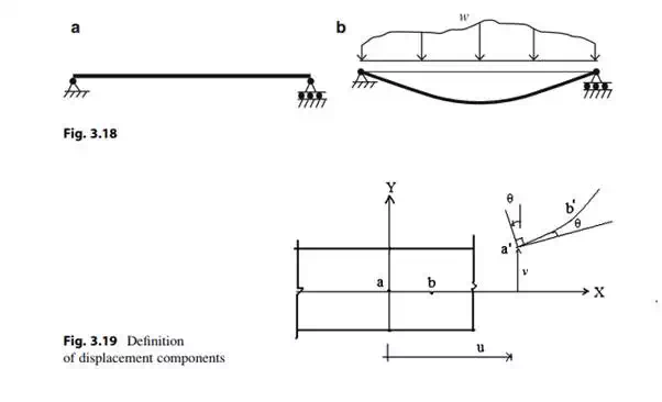
Figure 3.18 shows how a slender beam responds to a transverse planar loading. The geometric quantities that define the movement of the beam from its unloaded position due to an applied loading are defined as the displacements. Displacements are also referred to as deflections. Consider the segment of a homogeneous beam shown in Fig. 3.19. We take the X-axis to coincide with the initial position of the centroidal axis, and the Y-axis to be 90 degree counter clockwise from the X-axis. When the loading is applied in the X–Y plane, points on the centroidal axis move horizontally and vertically. We assume the cross-section, which is initially normal to the centroidal axis, remains normal to the curve connecting the displaced points. This is a standard assumption for beams known as “Kirchoff’s” hypothesis and implies that the cross-section rotates through the same angle as the tangent to the centroidal axis. Kirchoff’s hypothesis is valid for slender beams, i.e., beams having a depth to span ratio less than about 0.1. With this assumption, the independent geometric measures are the two displacement components, u(x) and n(x), which are functions of x for static loading. Given vðxÞ, we find the cross-sectional rotation, y(x), with the geometric relation,


According to this model, the strain varies linearly over the cross-section and the peak strain values occur at the upper and lower surfaces; the centroidal axis is not strained.
At this point, we introduce some standard notation for the derivative of the cross section rotation angle, y.

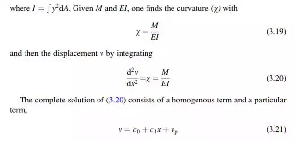
Given w, one can establish qualitatively the shape of the curve defining the displaced centroidal axis. An analytical solution for the displacement, v, can also be determined by integrating.
Moment: Curvature Relationship
We have demonstrated how to establish the bending moment distribution corresponding to a given loading. We have also showed how the displacement field can be generated once the curvature is known. To find the displacements due to a given loading, we need to relate the moment and the corresponding curvature along the centroidal axis. Given this relationship, it is a fairly straightforward process to move from prescribed loading to the resulting displacement.
The positive sense of the bending moment on a positive cross-section is defined as counter clockwise. Then noting Fig. 3.21, the moment and normal stress are related by

We determine the stress using the stress–strain relation. In what follows, we assume the material behavior is linear elastic. The stress is a linear function of the strain in this case.
![]()
where E is Young’s modulus for the material. Substituting for s in (3.16) leads to
![]()

