Deformation–Displacement Relations
Consider the planar truss structure shown in Fig. 2.22. Suppose the members experience deformation and one wants to determine the final position of node B. Our approach is based on first temporarily disconnecting the members at B, allowing the member deformations to occur, and then rotating the members such that they are reconnected. The movements of the nodes from the original configuration to the new configuration are defined as the displacements. These quantities are usually referred to a global reference frame having axes X and Y and corresponding displacement components u and v.
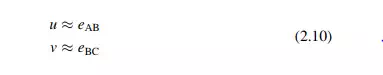
For structural materials such as steel, the extensions are small in comparison to the original length. Then, the member rotations will also be small. Noting Fig. 2.22b, and the above assumptions, it follows that the displacements are related to the deformations by
The simplicity of this results is due to the fact that the structure’s geometry is simple (the members are orthogonal to the coordinate axes).
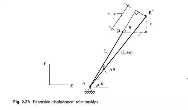
We consider the single member AB defined in Fig. 2.23. Our strategy is to track the motion of the end B as it experiences an extension, e. The final length is (L + e) where e is the extension. We assume Dy is small and project the final length onto the original direction. This step provides a first order estimate for the extension in terms of the nodal displacements. E
![]()
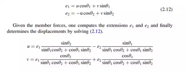
We consider next a two member planar truss shown in Fig. 2.24. Since the member orientations are arbitrary, the deformation–displacement relations will involve all the displacement components.
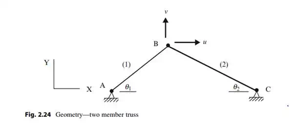
Applying (2.11) to the above structure leads to
Method of Virtual Forces
The formulation described in the previous section is not convenient for manual computation, even for fairly simple trusses. However, there is an alternative procedure called the Virtual Force Method, which avoids the need to solve simultaneous equations. Engineers prefer this approach since it is based on executing a set of force equilibrium analyses, a task that they are more familiar with.
The Method of Virtual Forces is a procedure for determining the deflection at a particular point in a structure given that the member forces are known. A general proof of the method can be found in [16]. We apply the method here for truss type structures. Later in the following chapters, we apply the procedure to beam and frame type structures. The method is restricted to static loading and geometrically linear behavior, i.e., where the displacements are small. This is not a serious restriction for civil structures such as building and bridges.
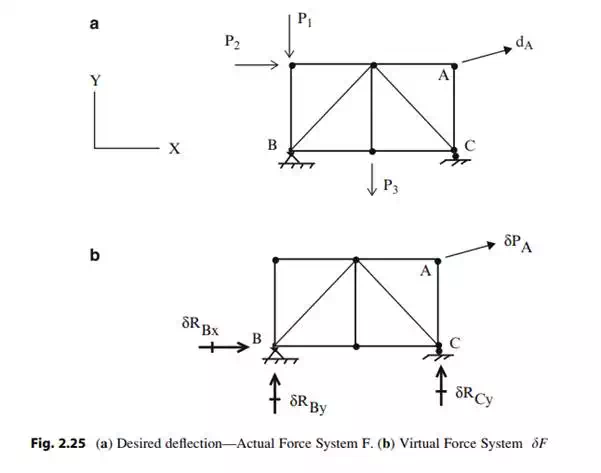
Consider a typical truss shown in Fig. 2.25a. Suppose the deflection, dA, in a specified direction at point A is desired. One applies a virtual force, dPA, at A in the specified desired direction and computes the corresponding member forces, dF, and reactions, dR, using only the static equilibrium equations. Usually one takes dPA to be a unit load. Note that this virtual force system is “specialized” for the particular displacement that one is seeking. The displacement is determined using the following expression:
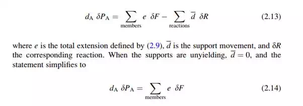
Given the actual forces, one evaluates e with (2.9), then determines the product, e dF, and lastly sums over the members. Applying (2.13) is equivalent to solving the set of simultaneous equations relating the deformations and the displacements. The following example illustrates this point.