Analysis of Planar Trusses
In this section, we focus on introducing analysis and behavior issues for planar trusses. The discussion is extended in the next section to deal with threedimensional space structures.
The analysis of trusses is based on the following idealizations that ensure that the forces in the members are purely axial:
1. The loads and displacement restraints are applied only at the nodes.
2. The members are connected with frictionless pins so that the members can rotate freely and no moment exists at the ends.
3. The stress due to the weight of the members is small in comparison to the stress due to the applied loads.
4. Each member is straight and is arranged such that its centroidal axis coincides with the line connecting the nodal points.
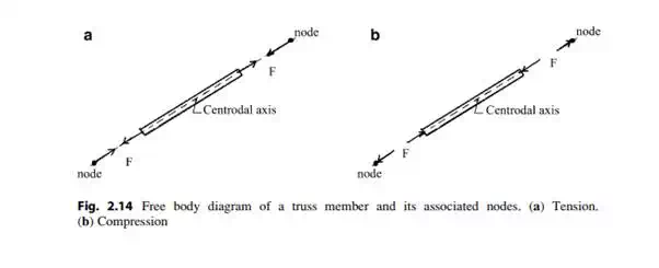
With these restrictions, it follows that a member is subjected only to an axial force at each end. These forces are equal in magnitude and their line of action coincides with the centroidal axis of the member. There is only one unknown per member, the magnitude of the force. The resulting state is uniform axial stress throughout the member. Depending on the loading, the member force may be either tension or compression. Figure 2.14 illustrates free body diagrams for a truss member and its associated nodes.
Equilibrium Considerations
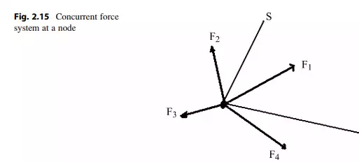
Each node of a plane truss is acted upon by a set of coplanar concurrent forces. There are no moments since the pins are frictionless and the lines of action of the forces intersect at the node. For equilibrium of a node, the resultant force vector must vanish. In Squire Whipple’s time (1840s), equilibrium was enforced using Leonardo da Vinci’s graphical method based on the force polygon. Now, one applies an analytical approach based on resolving the force vectors into components and summing the components. The corresponding scalar equilibrium equations are
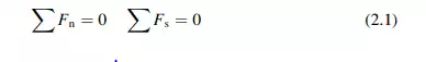
where n and s are two arbitrary nonparallel directions in the plane. Figure 2.15 illustrates this notation.
Statically Determinate Planar Trusses
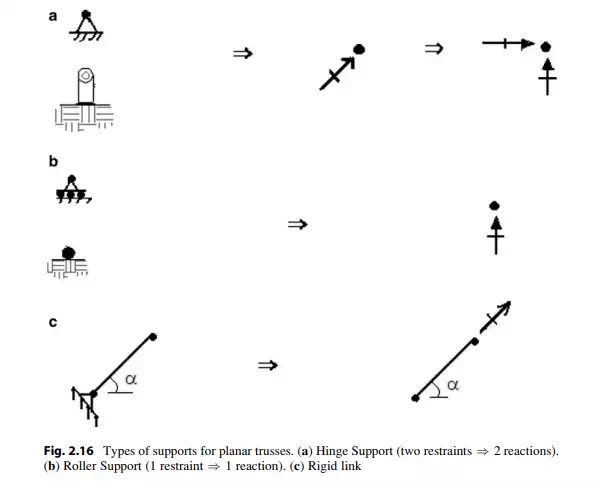
In general, three motion restraints are required to prevent rigid body motion of a planar truss. Two of these restraints may be parallel. However the third restraint cannot be parallel to the other two restraints since, in this case, the truss could translate in the direction normal to the parallel restraint direction. Each restraint generates an unknown force, called a reaction. Therefore, the minimum number of reactions is 3.
Examples of typical support motion restraints and the corresponding reactions are shown in Fig. 2.16.
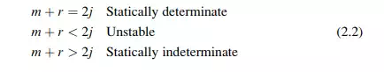
There are two scalar equilibrium equations per node for a plane truss. Assuming that there are j nodes, it follows that there are a total of 2j equilibrium equations available to determine the force unknowns. We suppose there are m members and r reactions. Then, since each member and each reaction involves only one unknown force magnitude, the total number of force unknowns is equal to m + r.
When the number of force unknowns is equal to the number of equilibrium equations, the structure is said to be statically determinate. If m + r < 2j, the truss is unstable since there are an insufficient number of either member forces or reactions or possibly both to equilibrate the applied loads. A word of caution: a statically determinate truss may also be unstable if the reactions are not properly aligned so as to prevent rigid body motion of the truss. We discuss this point in
more detail in the following section. It follows that a plane truss is statically determinate, unstable, or indeterminate when