Functional Safety Requirements and Design Flow
Functional safety refers to taking active measures for achieving the required risk reduction in two spheres: reliability and active safety.
This paper focuses only on how functional safety is deployed in the traditional RTL-to-GDS flow. In this section, we will review how functional safety analysis is used in the hardware design and verification flow to achieve the required risk reduction, i.e., the required hardware safety metrics.
FMEDA drives design exploration to meet the functional safety targets. In fact, by looking at failure modes and their metrics, it tells where to focus the design effort for meeting the constraints. It also directs the fault injection campaigns to get a direct, more accurate evaluation of the safety mechanism diagnostic coverage. DFA is performed instead, to ensure that proper measures are taken during the RTL-to-GDS flow to guarantee independence and avoid common-cause failures.
The selection of the best safety mechanism for a specific building block needs careful analysis of the tradeoffs between effectiveness and cost as power consumption, area, safety metrics, and timing performance all must be evaluated.
Safety mechanisms can be software tests implemented in the software stack, or hardware tests that are manually crafted into the RTL, or automatically inserted through the design flow. This paper only focuses on the latter.
Design and Implementation
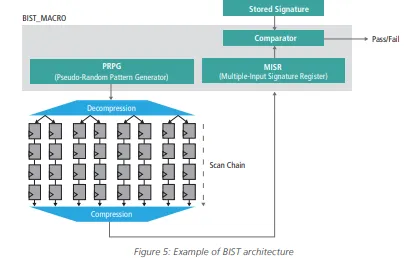
The most notable example of safety mechanism already automated in the design flow is the BIST, used for automotive in-system/field testing for lifetime reliability to achieve the desired ASIL.
There are two general categories of BIST techniques for testing random logic (Wang). They have different impacts on the safety metrics and require different timing performance:
• Online BIST: This test is performed when the functional circuitry is in normal operational mode (mission mode). It contributes to the SPFM metric and has more stringent timing requirements because it must complete within the DTI.
• Offline BIST: This test is performed when the functional circuitry is not in normal mode, e.g., during power-on reset at the engine startup. It contributes to the LFM and timing requirements are more relaxed.
Challenges to be addressed during BIST integration are speed testing capabilities, power consumption, area, routing minimization, and ASIL target (Wang). The integration of compression techniques provides quality and efficient sharing of resources (Pateras).
Although correlated, the test coverage estimated during BIST insertion is not exactly the DC required by the ISO 26262 metrics; functional safety verification might be needed to accurately measure the DC. Referring to the AEB system example in Figure 5, BIST can be used to avoid accumulation faults in the cache of a CPU (a typical issue in complex microprocessors).
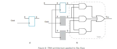
Another example of a safety mechanism is the triple modular redundancy (TMR) technique. In this case, the logic (memory cell) sensitive to single-event-upsets is tripled and voters are placed at the outputs to identify the correct value (Ruano). Figure 6 shows a TMR architecture applied at the flip-flop level: this technique covers both SPFM and LFM for the sequential elements that are triplicated.
Whenever the safety architecture is based on hardware redundancy, DFA needs to be performed to address common-cause failure due to random physical root causes: essentially, logical independence needs to translate into physical independence
Another safety mechanism based on redundancy is the dual-core lockstep (DCLS), also mentioned in Table 2. Both shared resources (e.g., power supply, clock, reset signal) and single physical root cause must be considered as potential common cause failures and require special design techniques to keep a high achievable DC.
Figure 7 reports examples of countermeasures to address the common cause failure at the functional level, such as timing diversity and outputs inversion. It also shows layout techniques to avoid cross-talk or guarantee strong isolation between redundant blocks (e.g., ring barrier). Several place and route constraints are implemented to guarantee physical independence, e.g., same value register spacing and safety coloring for power-domain routing.
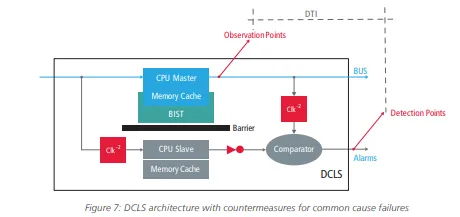
Figure 8 shows an example of a design implemented with and without functional safety routing constraints using the Cadence® Innovus™ Implementation System: the bottom-left region is the main copy of a block, while the top-right region is the replica inserted for redundancy. By guaranteeing that wires belonging to the main block can never go into the top-right region, the redundant blocks are physically independent by construction and meet requirements of the DFA.