Basics of Functional Safety
In this section, we review the basic concepts of functional safety, its lifecycle and the analysis techniques
Definition of Functional Safety
ISO 26262: Road Vehicles—Functional Safety is the automotive industry standard, derivative of the more general IEC 61508 functional safety standard (IEC), designed for safety-related systems for series production passenger vehicles with a maximum gross vehicle mass up to 3,500 kg and that are equipped with one or more E/E subsystems (Beckers).
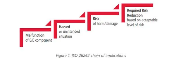
According to ISO 26262, functional safety is defined as the “absence of unreasonable risk due to hazards caused by malfunctioning behavior of electrical/electronic systems”.
This definition can be represented as a chain of implications, as shown in Figure 1.
Failure Classification and Hardware Random Failure Metrics
Per ISO 26262, malfunction of the electrical/electronic (E/E) component is classified into two types of failures:
• Systematic failures: These represent the failures in an item/function that are induced in a deterministic way during development, manufacturing, or maintenance (process issues). These failures—typically due to process causes—can be addressed by a change of the design or of the manufacturing process, operational procedures, documentation, or other relevant factors. Typical requirements are tracking and traceability. All these methods and expectation are captured by the functional safety management activities as reported in ISO 26262-2:2011.
• Random failures: Hardware random failures appear during the lifetime of a hardware element and emanate from random defects innate to the process or usage conditions. Hardware random failures can be further classified in permanent faults (e.g., stuck-at faults) and transient faults (e.g., single-event-upsets or soft errors).
Handling random failures is addressed during the design and verification of the hardware/software system by introducing safety mechanisms to make the architecture able to detect and correct the malfunctions.
From the vocabulary in ISO 26262:1-2011, a safety mechanism is a technical solution implemented by E/E functions or elements, or by other technologies, to detect faults or control failures to achieve or maintain a safe state.
Examples of safety mechanisms include:
– Error correction code (ECC)
– Cyclic redundancy check (CRC)
– Hardware redundancy
– Built-in-self-test (BIST)
The effectiveness of the solution to detect these random failures is measured by three metrics to detect fault and failure in time (FIT), as well as the overall likelihood of risk:
Single-point fault metric (SPFM)
– Latent fault metric (LFM)
– Probabilistic metrics for hardware failures (PMHF)
These three metrics are essentially the measurement of functional safety for hardware components per ISO 26262 and the rest of this paper mainly focuses on how to analyze them and meet their target value.
The description and formulas that define the hardware architectural metrics are reported in ISO 26262-5:2011, Annex D, C.2 and C.3 and 9.2:
• Single-point fault metric: This metric reflects the robustness of an item/function to the single-point faults either by design or by coverage from safety procedures.
• Latent fault metric: This metric reflects the robustness of an item/function against latent faults either by design (primarily safe faults), fault coverage via safety procedures, or by the driver’s recognition of a fault’s existence before the infraction of a safety objective.
• Probabilistic metric of hardware failures: This metric provides rationale that the residual risk of a safety goal violation due to random hardware failures is sufficiently low (Chang).
In an intuitive way, a single-point fault can lead directly to the violation of a safety goal, while a latent fault is an undetected fault that allows another fault to cause a hazard.