Operational Validation of Search and Rescue Robots
As shown in the previous chapters of this book, the ICARUS project developed multiple unmanned systems and tools for supporting search and rescue (SAR) teams. These technological tools were developed after a careful consideration of the end‐user needs, as discussed in Chapter 2 of this book. Of course, during and at the end of the design lifecycle, the performance of the different tools with respect to the user requirements and target performance levels needs to be evaluated. This process of system validation requires a careful compromise between two points of view:
1. End users want validation tests to occur in realistic operational conditions, mimicking as closely as possible a real deployment.
2. Scientists want validation tests to have statistical relevance, so they want repeated tests, performed under controlled environments. However, it is very hard to quantify the system performance in a rigorous scientific manner due to the fact that many variables are out of control in an outdoor environment, e.g. the weather conditions (wind, rain, sea state, illuminance, etc.). Moreover, a scientific evaluation requires that multiple trials must be held to validate the statistical significance of the quantitative results, which is not evident when confronted with the evaluation of complex heterogeneous robotic teams in operational conditions, requiring significant logistics for setting up each trial run.
In the past, multiple proposals have been made in order to combine these different points of view. As a result, validation methodologies can be generally categorized into two approaches:
1. The first approach is based on the development of highly standardized test methodologies. A good example is that developed and proposed by the National Institute of Standards and Technology (NIST). The big advantage of these methodologies is that they allow to accurately quantify the performance of the robots in a number of test setups. The disadvantage of these methods is that, due to their standardized nature, these approaches are often quite dissociated from practical operational conditions.
2. The second approach for validation is robot competitions like DARPA, euRathlon and ELROB. Here, multiple robotic systems are pitted against each other in more or less realistic operating conditions. The advantage of this validation approach is that the performance can be evaluated in real‐life like circumstances and environments. The disadvantage of these kinds of benchmarking methodologies is that, due to their non‐standardized nature, they often only allow a qualitative appreciation of the robot performance and do not allow making a detailed quantitative measurement. Another important disadvantage is that coincidence (e.g. dependence on singular element failures that may not be exemplar for the overall system operation, changing weather and lighting conditions between trial runs, etc.) plays an important role in these competitions, which significantly compromises the statistical significance of the benchmarking result.
It is clear that both of these approaches are highly valuable and necessary. However, none of them gives an ultimate solution for the performance evaluation problem. Here, we present the operational test and validation approach for the evaluation of the performance of a range of marine, aerial and ground search and rescue robots. This methodology has been proposed and followed within the ICARUS project. The proposed approach aims to find a compromise between the traditional rigorous standardized approaches and the more open‐ended robot competitions. Following this methodology, operational scenarios are defined that include a performance assessment of individual robotic tools. Furthermore, these operational scenarios also assess the performance of heterogeneous teams of robotic tools, cooperating not only among robots, but also with manned teams in realistic search and rescue activities. In this way, it is possible to perform a more complete validation of the use of robotic tools in challenging real‐world scenarios.
The ICARUS project considers two main demonstrations to validate the tools developed during the whole duration of the project:
1. A marine demonstration, simulating a shipwreck in coastal waters.
2. A land demonstration, simulating an earthquake in an urban environment.
This chapter reports on the results of the operational validation performed during both demonstrations. However, the proof of the pudding is in the eating. No simulated disaster management exercise can mimic the chaos and difficult environmental conditions encountered during a real response operation. Therefore, we also included a section reporting on the use of one of the unmanned aerial systems deployed during a real flood‐relief operation, within the framework of the ICARUS project.
Maritime demonstration: simulated shipwreck response
GENERAL STORYBOARD
Organized in coordination with the yearly REX exercises, the scenario for the maritime demonstration is based on a shipwreck of a ferryboat. For such a scenario, the roles of the robotic tools can be separated according to the nature of the platforms. Aerial vehicles are used in search operations, sweeping the area and providing information about the exact location of the accident, localizing victims on the water and tracking them. Another role of the aerial segment is to carry mobile communication equipment allowing for the establishment of an extended range mobile network to support communications between all robotic assets and also with manned platforms. On the other hand, the main role of maritime platforms is on the rescue operations. Taking advantage of the data collected by the aerial segment, maritime platforms get close to located victims and assist them. Such assistance consists in providing floatation and shelter from environmental conditions, extending their time of life and allowing rescue in safe conditions.
LOCATION AND ORGANISATIONAL ISSUES
The sea demonstration took place on the Tagus river estuary in the area of the Lisboa Naval Base, located in Alfeite, Almada, Portugal, as shown in Figure 1. The selection of this place took into account several issues related to the demonstration: segregated area for the operation of unmanned systems, realistic scenario for a search and rescue operation, easy access to the operational area and for mounting command and control stations as well as communications equipment.

FIGURE 1.
Location of the sea demonstration area: Lisboa Naval Base in Portugal, showcasing the area reserved for the ICARUS sea demonstration (source: ICARUS).
Figure 1 shows the location of the ICARUS sea demonstration area, off the south bank of Tagus river estuary. This figure also exhibits the navigation lanes of ferryboats that continuously cross the estuary, a characteristic that was taken into account in the selection of a realistic location for the demonstration. Furthermore, the selection of a location right in front of the Lisboa Naval Base simplified the logistics associated to the operation due to the existence of local facilities from the Portuguese Navy and from the Arsenal do Alfeite Shipyard.
For the operations on the water, the region shown in Figure 1 was closed to maritime traffic, except for the vessels required for the demonstration and to patrol the area to make sure that unauthorized vessels do not enter it, so that all activities related to the demonstration could be carried out without major concerns with other activities that could cause any kind of interference. This area exceeds 2 km2 and the maximum distance from shore is about 2.2 km.
OPERATIONAL VALIDATION FOR MARITIME SEARCH AND RESCUE
Time: T0
Events: An explosion of unknown origin occurs in a ferryboat crossing the Tagus river estuary near Lisboa. Victims fall in the water. The ferryboat, shown in Figure 2, starts sinking.

FIGURE 2.
Ferryboat used for simulating the shipwreck accident (source: ICARUS).
Time: T0 + 0h05min
Events: The Marine Rescue Coordination Center (MRCC) in Lisboa receives an alert describing the accident and its approximate location. After an initial assessment, the MRCC dispatches to the area search and rescue teams (including robotic assets).
Time: T0 + 0h40min
Events: Search and rescue teams start arriving at the location of the accident (riverbank). A local coordination centre, shown in Figure 3, is set up where the ICARUS command and control system is deployed and communications with MRCC are established. Search and rescue assets, including manned rigid‐hulled inflatable boats and unmanned aerial and surface vehicles, are prepared for launching.

FIGURE 3.
Set‐up of ICARUS command and control tools at the local coordination centre. (source: ICARUS).
Evaluation: For a search and rescue mission where every minute counts, the set‐up time for the developed technological tools is still an important factor where progress can be made. Confronted with the complicated frequency spectrum in the Lisbon harbour environment, it was mainly the configuration of the communication tools which increased the overall set‐up time.
Time: T0 + 1h00min
Events: An area around the approximate location of the accident is defined and a fixed wing long endurance unmanned aircraft is deployed to make a survey of that area, as shown in Figure 4.

FIGURE 4.
Initial area surveillance with the fixed wing long endurance unmanned aircraft (source: ICARUS).
Evaluation: Take‐off and landing operations of the fixed wing long endurance unmanned aircraft were performed manually by trained personnel. As the fixed wing long endurance unmanned aircraft is hand‐launched, take‐off is still quite easy, even in a cluttered environment. However, landing requires the careful choice of a suited landing position, which is tough in a heavily built‐up harbour environment. Luckily, the fixed wing long endurance unmanned aircraft can stay airborne for multiple hours (even days), so the issue does not occur often. In flight, the fixed wing long endurance unmanned aircraft semi‐autonomously executed a GPS‐defined trajectory and a search pattern mission over the area defined for the sea demonstration. A person external to the operating team provided the profile of this mission. Several flight patterns were tested and successfully performed by the fixed‐wing long‐endurance unmanned aircraft.
Time: T0 + 1h10min
Events: Images collected by the fixed wing long endurance unmanned aircraft start arriving at the local coordination centre and at the MRCC, providing information about the location of the ferryboat, victims on the water and debris scattered over the area, as shown on Figure 5.
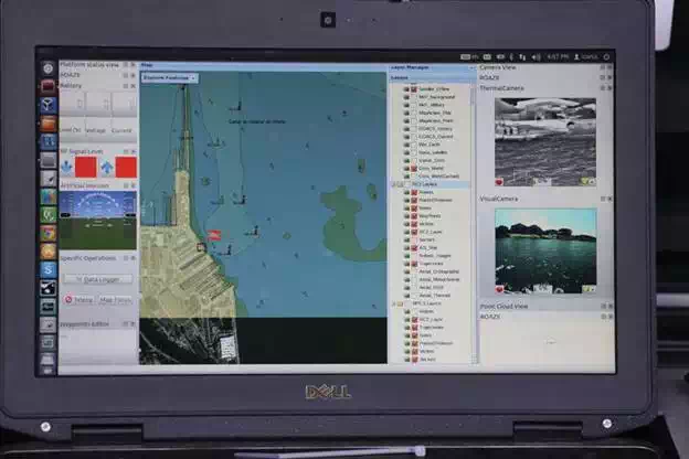
FIGURE 5.
Information being displayed on the command and control interface (source: ICARUS).
Evaluation: Live streams from the thermal and video camera on‐board the fixed wing long endurance unmanned aircraft were received at the command and control interface. Victim positions were also transferred to the command station.
Time: T0 + 1h20min
Events: Based on the information collected by the fixed wing long endurance unmanned aircraft, the rescue operation is planned at the MRCC: areas of intervention are assigned to manned rigid‐hulled inflatable boats and carrier unmanned surface vehicles. The MRCC sends operation plans to local coordination centre; these plans are received by the command and control station of robotic assets and rescue operations start.
Evaluation: In order to test the detection capabilities of the different assets, the victims in the water were asynchronously spread over multiple clusters: there were clusters with one person, two persons and four persons. The relatively high‐altitude fixed wing long endurance unmanned aircraft proved to be able to spot the clusters of victims in the water, but was unable to count the number of victims per cluster, due to limitations in sensor resolution and the high flight altitude.
Time: T0 + 1h30min
Events: Carrier unmanned surface vehicles head to clusters of victims located further away; at the same time, the rotary wing unmanned aircraft is launched to track victims that will be rescued by unmanned capsules on‐board two carrier unmanned surface vehicles: the ROAZ II and the U‐RANGER, as shown on Figure 6. Manned rigid‐hulled inflatable boats also depart to rescue people closer to the margin, while another unmanned capsule is deployed and remotely piloted towards victims that are close to the margin.

FIGURE 6.
Rotary wing unmanned aircraft providing victim’s location to ROAZ II (source: ICARUS).
Evaluation: Similar to the endurance aircraft, the take‐off and landing of the rotary wing unmanned aircraft were performed manually and mapping and victim search were executed semi‐autonomously. For legal and safety reasons, the U‐RANGER always operated with a person on‐board. Besides the command and control interface that remotely operated the unmanned surface vehicle, a second backup control station was used to create another safety loop. Contrary to the fixed‐wing long‐endurance unmanned aircraft, the rotary‐wing unmanned aircraft proved to be capable of not only detecting the clusters of victims but also of counting the number of victims per cluster, which provided important information for the allocation of resources. Space management between manned and unmanned assets was an important factor in this phase of validation, as multiple simultaneous rescue operations started in the same area. This incurred that the U‐RANGER could not operate at full speed due to safety reasons, but due to the intelligent obstacle avoidance capabilities of the unmanned systems, no problems occurred.
Time: T0 + 1h40min
Events: One carrier unmanned surface vehicle arrives near a first cluster of victims and deploys one unmanned capsule, as shown on Figure 8. This unmanned capsule is remotely operated to move towards the victims using location information provided by the rotary‐wing unmanned aircraft, as shown on Figure 7. When the unmanned capsule arrives close to the victims, as shown on Figure 9, it inflates a life raft and victims start climbing on‐board the life raft.

FIGURE 7.
Rotary wing unmanned aircraft providing victim location to an unmanned capsule (source: ICARUS).

FIGURE 8.
Unmanned capsule being launched from ROAZ II (source: ICARUS).

FIGURE 9.
Victim being rescued by an unmanned capsule (source: ICARUS).
Evaluation: Once started, the rescue operations moved very quickly. During the whole operation, live video feeds from thermal and visible cameras were received at the base station console. Radar and laser data used to detect obstacles on the water were also transmitted to shore.
Time: T0 + 1h45min
Events: The same carrier unmanned surface vehicle moves now towards another cluster of victims. The rotary wing unmanned aircraft tracks the location of these victims that are drifting away due to the water current. Another unmanned capsule is launched and automatically moves towards the victims using information provided by the rotary wing unmanned aircraft. Again, it inflates the life raft when close to the victims. Meanwhile, the other unmanned surface vehicle also deploys an unmanned capsule; this unmanned capsule moves autonomously towards a location where victims were spotted; the life raft is inflated by direct action of the victims. By that time, the unmanned capsule launched from the riverbank already reached the victims and its life raft is inflated.
Evaluation: Simultaneous rescue operations normally provide a cognitive overload for the commander in charge of the operation, but thanks to the ecologic display functionalities of the ICARUS command and control system, the commander could keep an overview of the different operations and coordinate the instructions towards the different team members.
Time: T0 + 1h50min
Events: The carrier unmanned surface vehicles head now to the area behind the sinking ferryboat, as shown on Figure 10; thermal and visible images are sent back to the local coordination centre for situation assessment. The aerial vehicles provide wireless links to the unmanned surface vehicles while they are operating out of sight.

FIGURE 10.
U‐RANGER and ROAZ II providing situational awareness to rescue workers behind the ferryboat (source: ICARUS).
Evaluation: The ferryboat blocked line of sight connectivity to the unmanned surface vehicles. However, the fixed wing long endurance unmanned aircraft acted as a relay station, providing connectivity to both vehicles, allowing for streaming real‐time video to the base station.
Time: T0 + 2h00min
Events: Information received from the unmanned surface vehicles is then used to plan a rescue operation for people still on the ferryboat. By that time, the robotic assets are recovered and their activities end.
CONCLUSIONS OF THE MARINE DEMONSTRATION
Besides the impact of the sea scenario demonstration in the media and the opportunity it provided for establishing contacts with stakeholders and other relevant players, the experiments conducted during the trials were used to obtain qualitative and quantitative information about the technical developments of the project and the way they met the established goals.
Such assessment was organized along the following lines:
1. Validation of capabilities. During the experiments, capabilities (sets of aggregated requirements) planned for each system or set of systems were assessed. A total of 71 of 84 capabilities were validated.
2. Performance analysis. Performance analysis consisted in assessing quantitative metrics against three performance targets (minimum acceptance, goal and breakthrough levels). For the total of 66 metrics considered, 36 (55%) reached the breakthrough level, 18 (27%) reached the goal level, 11 (17%) reached the minimum acceptance level and just 1 (2%) was below this minimum level.
Two officers from the Portuguese Navy were asked to evaluate the individual platform experiments, either when they were conducted independently or while they were carried out as part of more complex tests. In each case, they were asked to score the experiment and provide some comments. The feedback provided were extremely positive and in line with the other evaluation methods.
Land demonstration: simulated earthquake response
GENERAL STORYBOARD AND SETTING
In order to validate the performance of the ICARUS tools in an urban search and rescue context, the ICARUS land demonstration defines an earthquake‐response scenario where the different ICARUS aerial and ground assets are used to support the relief teams. The ICARUS land demonstration was integrated into a training exercise of the Belgian First Aid and Support Team (B‐FAST) as a preparation for their INSARAG IEC re‐classification tests. As such, the complete integration of unmanned tools in the standard operating procedures of real search and rescue workers could be tested.
The ICARUS land validation took place in the military base Camp Roi Albert in Marche‐en‐Famenne, Belgium, a woody and hilly area halfway between Brussels and Luxemburg. The base is the regular training ground for the B‐FAST team and provides for this purpose a rubble field with a pancake house for performing victim search and rescue operations and a built‐up area which can serve as a mock‐up urban setting for testing urban search and rescue protocols.
Figure 11 shows the different areas within the simulated crisis area which were used throughout the operations:

FIGURE 11.
Situational overview of the crisis area (source: ICARUS).
● The Base of Operations (BoO) set up by the B‐FAST team.
● The location of the city of Focagne, which is the urban area assigned to the B‐FAST team.
● The Forward BoO which is set up by B‐FAST close to the Focagne city.
● The road from the BoO to the Forward BoO which is partially blocked by debris.
● Apartment buildings which have collapsed and where victims could be found in the voids between the rubble.
● A semi‐demolished school building where trapped school children are present.
● A warehouse on fire with chemical products inside.
In the rest of this section, we will explain how the different ICARUS tools assist the search and rescue workers in dealing with each of the presented difficulties.
INTEGRATION OF THE ICARUS SYSTEM INTO THE OSOCC
Events: As shown on Figure 12, the B‐FAST Urban Search and Rescue (USAR) team sets up the On‐Site Operations Coordination Centre (OSOCC)‐level C4I equipment which includes a large workstation with displays. The USAR team’s communication specialist sets up local communication equipment and tests to see if web access and local GSM networks are available. The ICARUS C4I systems then connect to the Global Disaster Alert and Communication System (GDACS) and pulls in the latest data about the disaster.

FIGURE 12.
OSOCC set up by the B‐FAST team, serving as base command station for the operations (source: ICARUS).
Evaluation: The ICARUS command and control system was successfully connected to the OSOCC and imported GIS data, fact sheet data and GDACS data about the disaster. The end users did evaluate the total setup time of the whole system (1 hour) as still too slow. The main issue is communication, which is of course not an easy parameter to quantify and debug, as the communication ecosystem and frequency spectrum usage will be different in every crisis.
SUPPORT TO MISSION PLANNING
Events: As very little information is available, the planning officials of the team decide to use unmanned tools to obtain quickly a better common operational picture of the situation. The B‐FAST team leader orders the fixed wing endurance aircraft to scan the city of Focagne, as shown on Figure 13. The human operator at the BoO selects a geo‐referenced scan on the human‐machine interface, after which the aircraft executes the task semi‐autonomously. The goal of this first scan is to do obtain a good overview of the level of destruction in Focagne.

FIGURE 13.
Launching the endurance aircraft during the demonstration (source: ICARUS).
Evaluation: The UAS autonomously acquired data (visual + IR imaging) over the area of interest and transmitted this data in real time to the base station. The data from the UAS were used to reconstruct a map, which the mission planner overlapped with the pre‐existing GIS data. Based on the obtained information, the mission planner used the command and control system for sectorization. More detailed scans per sector were then performed.
End users were very impressed with the speed of obtaining a high‐quality situational overview of the crisis area using the data gathered by the aircraft via the ICARUS command and control system and many positive remarks were voiced.
DEPLOYMENT OF THE USAR TEAM
Events: As shown on Figure 14, the USAR teams move towards and deploy into a sector assigned by the mission planner via the command and control system. The main purpose of this scenario is to test the (rapid) deployment capabilities and the integration of the communication and command and control system. Another purpose of this scenario is to test the network and command and control system management capabilities when confronted with dynamic team and resource allocations and to test the capability of the aircraft to detect roadblocks.
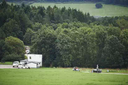
FIGURE 14.
B‐FAST team advancing with all ICARUS tools: large UGV (driving in front), small UGV (packed on first vehicle), rotorcraft (airborne in the middle of the picture) and fixed wing aircraft (airborne, but not visible in this picture) (source: ICARUS).
Evaluation: The B‐FAST team moved from the base of operations towards the forward base of operations, together with all the ICARUS tools. Organising this scenario required convincing the end users of the added value the ICARUS tools could bring in this phase of the operation. Indeed, in the beginning, the end users were afraid that the ICARUS tools would needlessly delay the USAR deployment operation, whereas speed is a key issue of course in any search and rescue operation. For this deployment operation, mostly the large UGV posed issues as it is of course not as fast as a standard truck. The ICARUS team therefore worked hard on finding the right balance between teleoperation and autonomous guidance for driving the large UGV as fast as possible up the hill without slowing down the B‐FAST convoy. This succeeded very well, as the convoy could advance at a very normal speed during the public demonstration day, to the satisfaction of the B‐FAST users. The B‐FAST end users also highly appreciated the continuous live input from the outdoor rotorcraft, warning them about road blocks, which could save them valuable time in a real operation.
VICTIM SEARCH AND RESCUE IN DEMOLISHED APARTMENT BUILDINGS
Events: The USAR team rescues victims trapped in a semi‐demolished apartment building, helped by the ICARUS UGV and UAV systems. The main objective of this scenario is to test the assessment, search and rescue capabilities of the outdoor rotorcraft and the large UGV and their collaborative operation mode.
The fixed wing aircraft is sent to sector to perform long‐range human detection using its infrared detector. It scans the area where the apartment buildings have collapsed. The UAS returned a map indicating the locations of potential victims. A mission to investigate the potential victim locations is transferred to the rotorcraft which is sent out to provide a high‐resolution 3D assessment of the site and to confirm the victim detections using its on‐board human detector, as shown on Figure 15. The rotorcraft returns from its mission. A very high‐resolution 3D map of the scan area is transferred, confirming the position of one undetected victim. The rotorcraft is sent out again to the victim location to assess the medical state of the victim. Analysis of the 3D map, imagery data and the victim location and medical state returned by the rotorcraft helps the planning team in setting up a plan to rescue the victims. Human rescue team members are sent out to rescue victims which can be evacuated without the help of the unmanned tools. The rotorcraft is (manually) equipped with a rescue kit and is requested to deliver this rescue kit to a victim which is trapped in the middle of the remains of the demolished building, as shown on Figure 16. The large UGV has cleared a pathway to the victim, as shown on Figure 17. The human rescue team comes in and evacuates the victim. The canine rescue team has located another victim below the rubble. However, due to structural instability, the access to the victim is considered too risky for direct human intervention. The canine rescue team sends the data on the victim location to the RC2 using their mobile devices and request the intervention of the large UGV for shoring the access path to the victim. Upon receiving this task, the large UGV first heads (remotely controlled) to the local command station to pick up few hydraulic/pneumatic struts. The large UGV is in place to start the shoring operation, with all tools at hand. The large UGV uses its manipulator arm, remotely controlled using an exoskeleton, to place the struts, as shown on Figure 18. The struts are activated remotely by a human operator. The large UGV has stabilised the entrance towards the sixth victim. Human rescue team members enter and evacuate the victim.

FIGURE 15.
Simultaneous aerial victim search operations at different altitudes (source: ICARUS).
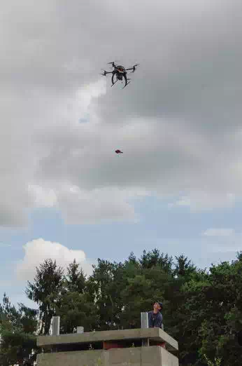
FIGURE 16.
Rescue kit delivery (source: ICARUS).
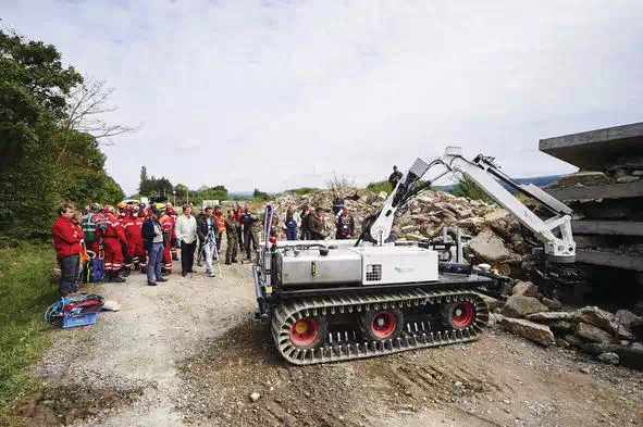
FIGURE 17.
Debris clearance with the large UGV (source: ICARUS).
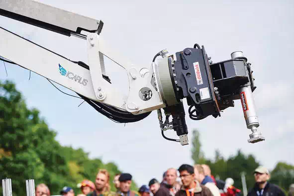
FIGURE 18.
Shoring operation with the large UGV (source: ICARUS).
Evaluation: End users and stakeholders were impressed by the seamless integration and collaboration as a team of ICARUS tools in the B‐FAST search and rescue toolkit. The complementarity between canine and unmanned aerial search teams was applauded as extremely useful for future SAR operations.
VICTIM SEARCH AND RESCUE IN SEMI‐DEMOLISHED SCHOOL BUILDING
Event: The team now focuses its attention on the school building where multiple children are reported missing. The building is too unstable for human rescue workers to enter safely. Luckily, however, the access to this building is clear. As such, it is decided that the indoor rotorcraft and the small unmanned ground vehicle will be sent in simultaneously for assessing the structural integrity of the building, giving rescue workers a view of what is happening inside and for finding survivors.
The indoor rotorcraft enters the building by flying through a broken window, as shown on Figure 19, while the small unmanned ground vehicle enters through the doors and corridors, as shown on Figure 20. Simultaneously, they explore and map the building, as shown on Figure 21 both finding and localizing survivors with their infrared and visual sensors, as shown on Figure 22.
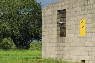
FIGURE 19.
Indoor rotorcraft entering the building via broken window (source: ICARUS).
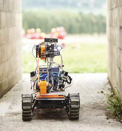
FIGURE 20.
Unmanned ground vehicle navigating through the corridors of the building (source: ICARUS).
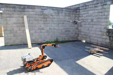
FIGURE 21.
Indoor rotorcraft and small UGV exploring the school building (source: ICARUS).
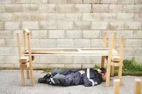
FIGURE 22.
Civil protection working acting as victim (obviously no real children could be used) (source: ICARUS).
The structural scans by the unmanned systems help the planning team in deciding that the rescue team can be safely sent into the building to rescue the victims detected and localized by the unmanned systems.
Evaluation: End users were positively surprised about the navigation capabilities in small enclosures of both the rotorcraft and the small UGV. Specifically, the capability of the rotorcraft of flying through window openings only marginally larger than its proper size generated much appraisal. For the indoor operations which happened beyond line of sight, radio connectivity was obviously problematic, so the semi‐autonomous exploration behaviours of both vehicles had to be used. While this led to a slower exploration strategy (notably for the ground vehicle) due to safety reasons, the whole planned operation could be completed within the time constraints.
VICTIM SEARCH AND RESCUE IN SEMI‐DEMOLISHED CBRN (CHEMICAL, BIOLOGICAL, RADIOLOGICAL AND NUCLEAR) WAREHOUSE
Event: The mayor reports that there is a two‐story warehouse with potentially dangerous products near the city centre. As previous attempts to enter the building without using the help of unmanned tools have failed and the structure is too unstable for the safe operation of humans near the walls, the help of all unmanned tools is requested for entering the building.
The large UGV is remotely controlled up to the building walls, as shown on Figure 23. With its manipulator arm, the large UGV deploys the small UGV which it was carrying onto a terrace on the first floor of the building, as shown on Figure 24. The small UGV moves to the door on the first floor. The exoskeleton is then used by a remote operator to control the manipulator arm on the small UGV to open the door, as shown on Figure 25 and Figure 26. The small UGV is now inside the building and starts scanning the surroundings, searching for victims and dangerous products and inspecting the structural integrity of the building. The complete building is explored by the small UGV and two human survivors are detected and localized. Meanwhile, the large UGV is standing guard close to the building entrance to act as a wireless repeater, ensuring optimal communication to the small UGV inside and the outdoor rotorcraft is sent to explore the roof of the building to detect possible human survivors. The outdoor rotorcraft detects a human survivor on the rooftop. Visual inspection from the footage of the UAS also indicates that the emergency exits seem to be blocked, indicating that the survivors should be evacuated through the building. Based on the data provided by the rotorcraft and the small UGV, the rescue workers decide on the protective equipment to wear for entering the building and start the victim evacuation.
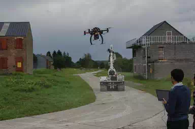
FIGURE 23.
Unmanned tools navigating to CBRN warehouse (source: ICARUS).
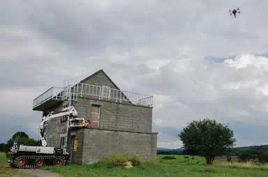
FIGURE 24.
Large UGV deploying small UGV on the first floor, assisted by the outdoor rotorcraft (source: ICARUS).
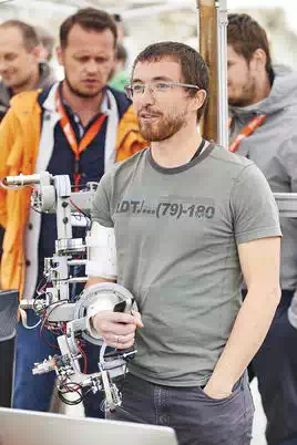
FIGURE 25.
Remote operator using an exoskeleton to operate the manipulator arm of the small UGV (source: ICARUS).
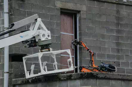
FIGURE 26.
Small UGV opening a door with the manipulator arm, remotely operated by the exoskeleton (source: ICARUS).
Evaluation: The public was impressed by the capability of the ICARUS command and control system to seamlessly manage the simultaneous operation of three unmanned tools (small UGV, large UGV and outdoor rotorcraft). Also the exoskeleton received a lot of attention and was praised by the spectators by its user‐friendliness. Many stakeholders present at the demonstration knew (some also from their own experience) that opening a door with a robot manipulator without direct line of sight for the operator is a notoriously difficult operation and they could not believe how seemingly effortless this operation was achieved via the exoskeleton.
CONCLUSIONS OF THE LAND DEMONSTRATION
Not less than five unmanned assets (large UGV, small UGV, fixed‐wing aircraft, outdoor rotorcraft and indoor rotorcraft) collaborated during the different land demonstration missions. All robotic assets were interfaced via the common ICARUS command and control interface, thereby showcasing the versatility and modularity of the ICARUS interoperability concept.
All victims who were hidden throughout the different missions were located in the end and received assistance, and a tight interrelation and even complete integration of ICARUS tools within the toolkit of the search and rescue workers was achieved.
As discussed before, a series of metrics and key performance indicators were defined by end users with detailed target performance levels to be attained by the different systems. For none of those metrics, a score was noted which formed a problem for global mission success. For 12% of the capabilities and metrics, the minimum acceptance level as imposed by the end users was reached, but the initially imposed target performance was not reached. For no less than 33% of the capabilities and metrics, the goal performance level as imposed by the end users was reached or even surpassed. Finally, for about half (47%) of the capabilities and metrics, consisting of the majority of the performance bins, a performance level which was indicated by the end users as “breakthrough‐level” prior to the demonstrations was reached. This number is an extraordinary achievement, showcasing that the ICARUS project succeeded in surpassing by far the expectations of the end users.
Real flood relief operation
MISSION CONTEXT
At the end of May and the beginning of June 2014, a catastrophic massive flooding occurred in Bosnia and Herzegovina, Croatia and Serbia due to abundant rainfall over the course of a few weeks. All countries suffered immense damage. In Bosnia and Herzegovina, where the whole northern region and part of the central region were heavily affected, it was estimated that 1.5 million people were affected (accounting to 39% of the population). Floods and landslides were responsible for at least 53 deaths in Bosnia and Herzegovina and Serbia.
In response to this catastrophe, the EU Civil Protection Mechanism was activated. Twenty‐two EU member states offered assistance through the mechanism. Figure 27 shows the flood situation and the deployment of international response teams, activated via the EU Civil Protection Mechanism. However, the relief efforts were hampered by the destroyed infrastructure, broken telecommunications, blackouts, etc.
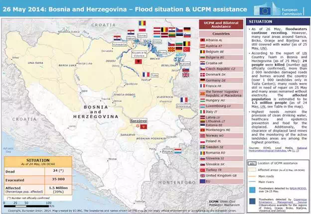
FIGURE 27.
Bosnia flood map (source: European Union Joint Research Centre—source: European Union 2014—used with permission).
Making matters worse, Bosnia and Herzegovina was contaminated with landmines due to the war that took place there from 1992 to 1995, and as a result, the country has one of the most serious landmine problems in the world. The presence of many explosive remnants of war (ERWs) remaining from the Balkan War of the 1990s created a very dangerous situation for the relief workers and the local population. The floods, torrents, landslides and land‐shifting had a destructive impact on the (previously mapped) suspected hazardous areas (SHAs) and minefields in Bosnia and Herzegovina. In Bosnia, 831.4 km2 of SHAs were flooded, and 37.48 km2 of SHAs in 33 locations were under direct impact of landslides and torrents. Due to the floods, the ERW started moving place and the SHAs had to be extended dramatically. By the 4th of July 2014, 1018 pieces of unexploded ordnance (UXO), 92 mines and 3 cluster bombs were already found, as well as 40,163 pieces of ammunition. Moreover, 80.2 km2of new areas that were previously not been suspected of having mines became potentially hazardous (mainly in the northern part of Bosnia and Herzegovina). The Bosnian Mine Action Centre (BHMAC) was immediately deployed and provided data and information about the affected regions, the types of influence, the impact intensity, the spatial distribution, as well as the priorities. Obviously, the problem of shifting minefields also hampered the provision of aid and relief, as well as the clearing of debris, as relief workers had to proceed with much care.
Among many other international Search and Rescue (SAR) teams, the Belgian First Aid and Support Team (B‐FAST), which is an ICARUS project partner, was deployed in Bosnia to help with relief operations. In order to put into practice the research efforts performed within the ICARUS project, the Belgian Royal Military Academy decided to send along with the B‐FAST team a UAV and a trained operator, together with 3D mapping tools, in order to assist the teams with tasks such as damage assessment, situational awareness, dike breach detection, mapping, aerial inspection and relocalizing the many ERWs that were displaced due to the landslides. The computing and data management tools described in Chapters 6, 8 and 9 were used in order to give the end users access to the data gathered by the unmanned system. This mission fitted perfectly in the framework of the European research projects ICARUS and TIRAMISU (on humanitarian demining). On the terrain, we were deployed in assistance to a team of the Bosnian Mine Action Centre in multiple regions of the country in order to localize the displaced ERWs. In a first phase, we provided support for urgent actions (urgent demining, assessment of status of minefields, etc.) by performing aerial surveys.
As we wanted to be fully incorporated into the deployment of the multiple international rescue teams, we first had a coordination meeting in the capital city of Sarajevo with the Bosnian Ministry of Security. After discussion with the Ministry of Security of Bosnia and Herzegovina and the national Directorate of Civil Aviation (BHDCA), flight permits for our operations were granted up to a flight altitude ceiling at 150 m for the complete Bosnian territory. Due to the crisis, and because all application documents for the flight permits were readily available (as they were already prepared for the previous operations), these flight permits were issued within half a day.
During a 2‐week period, we deployed a vertical take‐off and landing remotely piloted aircraft system at 13 locations in the north and central part of the country. In total, we performed about 20 flights within visual line of sight in semi‐urban and urban. Two types of operations were performed:
● Manual flights, where end users (demining or rescue teams) indicated interest points they wanted to see investigated by the UAV, mainly for damage assessment and visual inspection. A trained operator executed the flights themselves.
● Waypoint‐based mapping flights, where an area to be mapped was indicated by the end users. A flight plan for the UAV was then set up to map this area using an autonomous waypoint‐based flight. Also for these operations, a trained pilot always supervised the remote control station.
A typical flight lasted around 25 to 30 min, enabling us to cover an area of about 1 hectare. Multiple mapping missions were performed, gathering from 200 images to a maximum of 500 images, all with a resolution of 24 megapixels and mapping areas as large as 1 km2.
FLOOD RELIEF OPERATIONS
The Belgian B‐FAST team was deployed to the city of Orasje (located in the northeast), which was one of the cities that was hit most by the floods. The UAV was first deployed here to assist the B‐FAST team to monitor the water levels and to assess the optimal location to install the high‐pressure pumps, as shown in Figure 28. The problem with the installation of the water pumping system was that water levels were not decreasing after multiple days of pumping, due to an undetected dike breach.
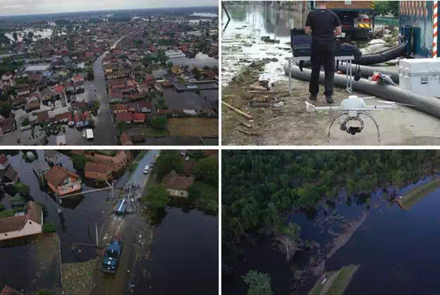
FIGURE 28.
Top left: Flooded city of Orasje; top right: UAV used for the operations; bottom left: optimization of the location for the B‐FAST water pumps and bottom right: broken dam on the Sava river detected by the UAV (source: ICARUS).
The ICARUS‐TIRAMISU UAV was able to locate this broken dam, as shown in Figure 28. Expert analysis of the UAV imagery indicated that this dam breach was not caused by natural means. As a result, the Bosnian Ministry of Justice has initiated a criminal investigation against the individual(s) who caused it and commissioned the ICARUS‐TIRAMISU UAV image material as evidence. The UAS proved very useful to quickly detect dike breaches and to map the area quickly. One of the main challenges was to find a landings spot on dry land, as there were virtually no spots of clear and open land suited for take‐off and landing. Due to these difficult operating conditions, all take‐off and landing operations were done via remote control by a trained pilot.
Next to the operations in support of B‐FAST, the UAV was also deployed at the request of the German Federal Agency for Technical Relief (THW) team and Austrian relief workers working at the incident site. These teams asked for the help of our UAV system for damage analysis, aerial inspection, improving their situational awareness and for selecting the optimal location for the installation of the high‐pressure water pumps. The Ministry of Security and the Federal Civil Protection of Bosnia and Herzegovina also requested for UAV support in the region of Kopanice (Southeast of Orasje), where the floodwaters from the Sava River broke through the local dams. The floodwaters flowed through the breaches and entirely submerged the farming lands, and all the people needed to be evacuated. The broken dam area was in a mine‐suspected region, making this mission especially risky.
DEMINING SUPPORT OPERATIONS
Another city that was hit hard by the floods and landslides was the city of Maglaj, shown in Figure 29. An extra problem in this region was the presence of many ERWs, making the deployment and work of the relief teams very dangerous. Therefore, it was decided to deploy the UAV system for inspection flights, specifically into areas that the relief teams could not easily access due to the mine risks. The UAV was used for aerial assessment and mapping of mine‐suspected areas and to find indicators of where the minefields were shifted due to the floods and landslides. Figure 29 shows such a reallocated minefield due to landslides. The data of the UAV was very important in assessing the ground movement due to landslides, as shown in Figure 29. From this information, experts could deduce the area where the landmines were moved to, which allowed to drastically reduce the search areas.
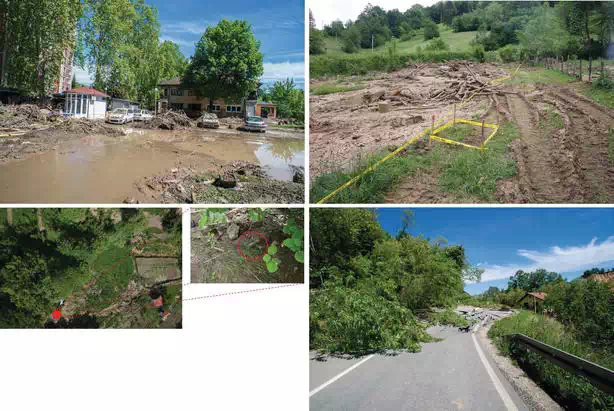
FIGURE 29.
Top left: City of Maglaj; top right: re‐location of mines due to the landslides; bottom left: detected anti‐personnel mine (mine moved due to the landslides); bottom right: damage assessment for mapping infrastructure damage) (source: ICARUS).
Figure 30 and Figure 31 show the initial post‐processing results of the Dolac region in central Bosnia and Herzegovina. The UAV was used in this region for providing orthophotos, 3D maps and Digital Elevation Models of the environment to analyse the effects of the landslides on mines and ERWs. These results were used as initial models by BHMAC for spatial estimation of new hazardous risks caused by the movement of unexploded ordnance (UXO) and landmines to areas that were not mine‐infested before the disaster. Combining the data from the UAV (3D Digital Terrain Models) with pre‐existing data (mine risk maps from the Mine Action Centres and satellite imaging), it was possible for experts to predict the movement of the landmines and to create updated maps of mine‐affected areas and mine risk map. To give an indication of the scale of the problem: some mines were found up to 23 km from their original location. If mines can move over such long distances, this means that the search area is enormous and it also means that area reduction techniques, such as the use of UAVs, combined with 3D mapping tools predicting the ERW movements and limiting the search area, have a major impact in the disaster‐response operation. More detailed information about this mission can be found in [14].
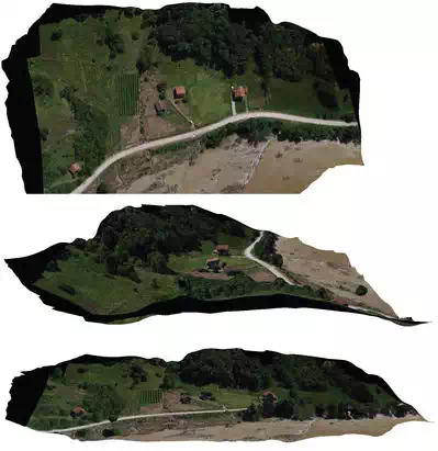
FIGURE 30.
High‐resolution orthomosaic of a mine‐affected area (source: ICARUS).
DATA FUSION AND SHARING
While the UAV tool provided a wealth of 3D information, one issue was that this valuable data had to be distributed quickly and securely to widely dispersed stakeholders (Bosnia and Herzegovina Ministry of Security, demining experts within the Mine Action Centre and deployed international search and rescue teams). An important constraint for doing this was that these stakeholders in general did not dispose of advanced 3D‐viewing tools. As a result, we decided to upload the gathered datasets to a cloud system (see Chapter 9). During this field operation, this was done by directly copying the datasets to the cloud system. We thereby tested the upload speed for a dataset of 500 MB, representing an average size of a dataset acquired by one sensor system (point clouds from a laser scanner or images from the digital camera of the UAS) for a single team area of operation (roughly 200 × 200 m). The results are shown in Table 1:
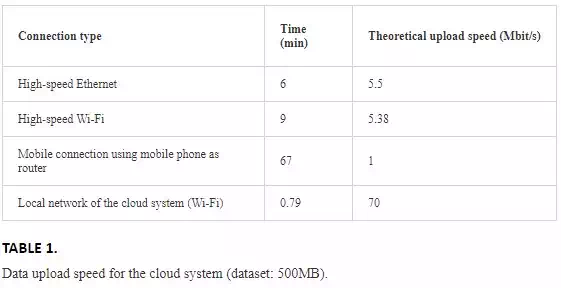
From our point of view, the best configuration is the local network of the cloud system, as it shows limited upload times inside the local cloud created by the server. After uploading and processing the datasets, they are immediately available to the end users for analysis and helping in the decision‐making processes. Data processing requires an operator to combine different types of datasets. The operator is also responsible for choosing the correct parameters for the different processing step and also evaluating the results. To facilitate the work of the operator, a set of recommended parameters were provided with a software module. The processed data were provided to the end users via a set of dedicated tools, focusing on efficient data visualization. This entire process is also secure (which is important, as UAV data is in general considered sensitive by governments), as the data itself is not passed directly, but in the form of renders. This also requires also only a very small amount of computation power on the local hardware of the end users. The provided server system is scalable, as it allows easy integration of extra software.
Using this tool, a demining expert from the Bosnia and Herzegovina Mine Action Centre was able to browse through the UAS data sets and make use of his prior experience for identifying indicators of mine presence under the destructive impact of the landslides and floods. He could define new maps of mine‐affected areas and create updated mine risk maps. This new information of the mine action situation could be easily shared via the cloud with other end users (mainly SAR teams in this case) in order to enhance their safety on the terrain.
CONCLUSIONS OF THE FLOOD RESPONSE OPERATION
Overall, the UAV mission proved to be a real success, based on the feedback provided by the end users. Some of their comments are as follows:
The first flight with the UAV was an assessment inspection of the flooding area where the B‐FAST water pumps were prepared. To get relevant information of this area from water and land would have cost us about 3 days. With the UAV we were able to provide even better results within 2 hours. With the second flight, we obtained a 3D model of the area on which the B‐FAST could determine the natural flow of the water. This information was not even attainable from the ground. (B‐FAST Team leader).
The results obtained by the UAV have been of the utmost importance during the response period, and also for post processing and investigation of future activities. (High ranked representative of the Ministry of Security Bosnia and Herzegovina).
The rapid mapping activities and the results we obtained from the UAV mission were crucial for damage assessment, and for relocalizing the many explosive remnants of war that were displaced due to the landslides and flooding. In that situation, we did not risk putting humans in the danger zones. (Technical operation officer of BHMAC).
This valuable feedback from the end users during a real relief mission clearly shows that the mission really had an impact on the terrain and that the use of novel technological tools developed within the ICARUS project in real search and rescue missions provides an added value.