Command and Control Systems for Search and Rescue Robots
This chapter describes the concepts and features behind the command, control and intelligence (C2I) system developed in the ICARUS project, which aims at improving crisis management with the use of unmanned search and rescue (SAR) robotic appliances embedded and integrated into existing infrastructures. A beneficial C2I system should assist the search and rescue process by enhancing first responder situational awareness, decision-making and crisis handling by designing intuitive user interfaces that convey detailed and extensive information about the crisis and its evolution.
The different components of C2I, their architectural and functional aspects are described along with the robot platform used for development and field testing in Figure 1. This section also provides an elicitation and analysis of the ICARUS C2I system requirements and the overall system and subsystem components’ architecture (hardware and software), along with the interfaces and data shared between these components. The objective is to provide a static and dynamic view of the structure and hierarchy within the components of this system.
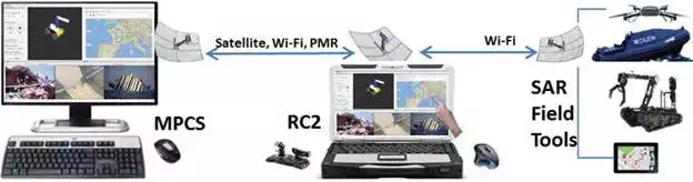
FIGURE 1.
C2I deployment and communication framework (source: ICARUS).
There have been recent efforts where C2I robots have been deployed for SAR, but the focus was mainly on human-robot cooperation, and there is no holistic approach to enable control of heterogeneous robotic assets. The requirement for customized robots and their control centres, equipped to provide a comprehensive common operational picture (COP) for SAR, is being addressed by the ICARUS C2I solutions.
In a disaster struck area, the local emergency management authority (LEMA) is responsible for the overall command, coordination and management of the response operation. The C2I system will provide extensive interfaces to incorporate unmanned systems, for augmenting the capabilities of SAR operation planning and execution. The seamless integration of human SAR teams with unmanned platforms is an integral feature of the C2I system.
The C2I system of ICARUS consists of a central mission planning and coordination system (MPCS), field portable robot command and control (RC2) subsystems, a portable force-feedback exoskeleton interface for robot arm tele-manipulation and field mobile devices. The deployment of C2I subsystems with their communication links for unmanned SAR operations is shown in Figure 2.
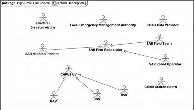
FIGURE 2.
Main actors involved in the C2I high-level use cases (source: ICARUS).
Approach to designing the C2I
STATE OF THE ART
Abstract mission planning and supervisory control is essential for deploying multiple unmanned systems for reconnaissance and mapping tasks, in large and open environments for extended durations. Commercial ground control stations are available for controlling and planning missions for single unmanned aerial vehicles (UAVs) such as Portable Ground Control Station and OpenPilot GCS. The availability of multi-UAV base control stations is not widespread, but limited to a few such as the QGroundControl. Apart from allowing users to plan UAV missions, these utilities are primarily designed for UAV development, debugging and testing. Supervisory interfaces for robot systems have been designed and developed, for instance, the DexROV control centre, to perform offline system training and online task monitoring for remote ROV operations. These interfaces still require humans constantly in the loop for performing low-level tasks and for coordinating tasks between unmanned systems. Deployment of Unmanned Ground Vehicles (UGV), Unmanned Aerial Vehicles (UAV) and Unmanned Surface Vehicles (USV) autonomously for long-endurance operations requires an approach as described in the Multimodal User Supervised Interface and Intelligent Control (MUSIIC) project. An ecological interface design analysis management operator centric needs will need to be performed to evaluate how the human cognitive system imposes constraints on the processing of information from multiple unmanned assets. Identifying the three levels of cognitive control—skill-based, rule-based and knowledge-based—is important for ensuring effectiveness of the supervisory control system for managing the unmanned fleet [16]. Displays for integrating information from different frames of reference, exocentric and egocentric, present potential human performance issues which need to be carefully evaluated. The supervisory control centre will be used only for high-level global mission planning and monitoring. The central command and control base station will be deployed near the port, capable of planning missions for UAVs and USVs to execute their tasks cooperatively. The graphical interface will be designed based on ecological design concepts to improve situational awareness.
END-USER INVOLVEMENT
Inputs and consideration of end-user requirements for the C2I system design are critical as it is the principle interface between them and the unmanned platforms in SAR scenarios. The ICARUS C2I is a complex system providing the end-users with multiple user interfaces at various operation levels. For example, the MPCS is aimed at mission managers and mission planners; the RC2 is aimed at robot operators, and the mobile application is for rescue workers. Work in the field of robotic control (user) interfaces has, for a long period, remained a research topic. Most user interfaces in use today are designed for specific end-users (fire fighters, soldiers, etc.), robotic platforms [unmanned ground vehicles (UGVs), USVs and UAVs] and applications (e.g. Explosive Ordnance Disposal EOD, reconnaissance and surveillance). In ICARUS, the challenge is to develop a unified system that enables control of heterogeneous robotics platforms.
For this complex system to work well with end-users, a user-centred design approach has been adopted. Contact was established with end-users to understand SAR processes and methods early in the project. Only after meetings with end-users and reviews of operational scenarios in the INSARAG guidelines was the concept for the ICARUS C2I proposed. The system requirements have been derived from the user requirements collected in the initial phases of the project. The system concept has been reviewed by B-FAST members with the general approach. However, it must be noted that the bespoke nature of the C2I, the unavailability of reference implementations and low user experience with robotic platforms make it difficult for end-users to provide usable feedback before early system prototypes are available. The approach taken was to invite end-users to review early prototypes and gather their feedback by initiating dialogs with B-FAST and setting up user-review meetings frequently.
HIGH-LEVEL AND DETAILED USE CASES
The high-level use cases of the ICARUS C2I system describe the main interactions of the system with the various actors (SAR users and other systems). The objective of the high-level use cases is to ensure that the C2I design concept adequately covers the main needs for Urban Search and Rescue (USAR) and Maritime Search and Rescue (MSAR) operations. It must be noted that the high-level use cases provide the reader with a broad view of the interactions of the different actors with the C2I. The main actors and their interrelationships are provided in Figure 2. The following actors are envisaged as the main users of the C2I system:
● Disaster victim
● Local emergency management authority (LEMA)
● Crisis data provider
● SAR first responder
● SAR mission planner
● SAR robot operator
● SAR field team
● Crisis stakeholders
● ICARUS unmanned vehicle (UV): UGV, UAV and USV
These use cases are developed under three main packages which have been identified based on the proposed USAR scenarios:
This package covers the use cases (Figure 3) of the C2I system in the context of mission planning. Mission planning will be the first task undertaken after setup of the hardware which includes and is not limited to disaster data analysis, area reduction, resource assessment and assignment, monitoring and coordinating actors and systems in the field, communications with stakeholders and revising and updating mission plans.
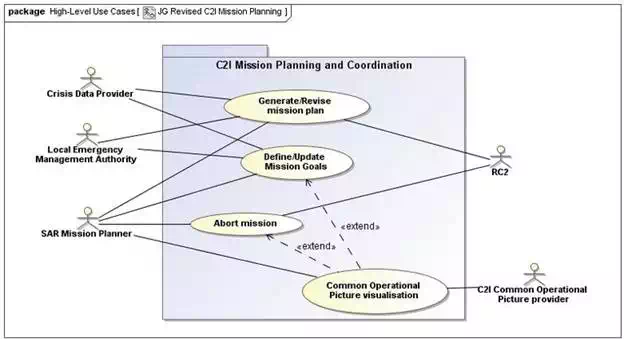
FIGURE 3.
C2I high-level use cases for mission planning and coordination (source: ICARUS).
The main robot command and control interactions with the actors and the C2I system are described in Figure 4. As a high-level use case, this includes the control of all ICARUS robotic systems. The following use-case packages have been identified to categorically group the interactions of the robot operator with the RC2 system:
● Robot mission execution: Tasks performed before and during the period one or more robots are deployed in a disaster zone.
● UAV command and control: These use cases describe the various interactions foreseen for UAV guidance, navigation and control.
● UGV command and control: The various interactions foreseen when the robot operator uses the UGVs for search and rescue operations.
● USV command and control: The use cases describe the interactions of the robot operator with the different unmanned surface vehicles.
● Heterogeneous command and control: The use cases specify the interactions of the robot operator under conditions where cooperative behaviour between pairs of robots is foreseen.
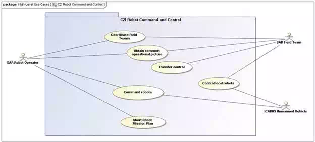
FIGURE 4.
C2I high-level use cases for robot command and control (source: ICARUS).
Figure 5 describes the principal lines of interactions for exchanging data between the C2I and field deployed actors to receive an updated common operational picture (COP) and to push updates to the C2I from field operations.
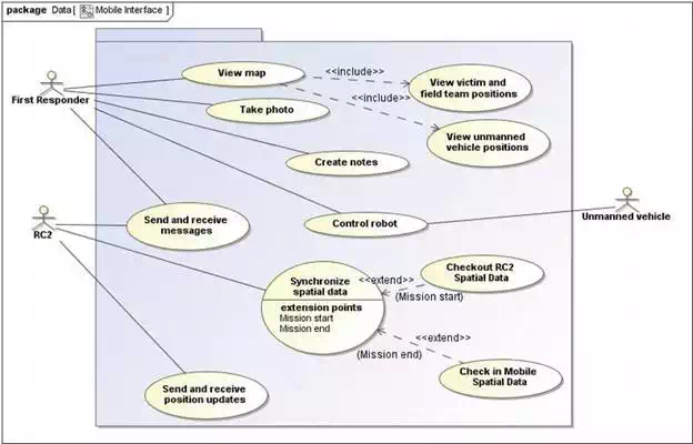
FIGURE 5.
Mobile interface for first responders’ main use cases (source: ICARUS).
SUBSYSTEM ANALYSIS
The C2I system will provide a variety of functions for SAR teams under the global objective of identifying disaster victims in a fast and efficient manner. Based on the high-level use-case analysis, the requirements can be classified and grouped into six major groups:
1. Mission planning and coordination tools and subsystems.
2. Command and control subsystems for unmanned vehicle control. This includes a force-feedback system for control of the robot arms mounted on the UGVs.
3. A mobile application to enable communications between the above systems and first responders working at the intervention site.
The main functionality provided by each of the above systems is described in the following sections.
The mission planning and coordination requirements for the C2I system illustrate the need for the availability of tools to help SAR mission planners to organize and deploy SAR human and robot teams in a disaster zone. Extending the requirements, this means that the C2I system must include a subsystem that allows SAR mission planners to create mission plans, monitor missions and make decisions to update or abort missions. This subsystem is titled as the mission planning and coordination subsystem (MPCS). The system provides the SAR mission planner with the ability to allocate SAR resources based on an analysis of crisis data. SAR resources could be allocated to specific crisis ‘sectors’ that are designated as critical by the SAR mission planner with the support of the MPC tools. During a mission, the MPCS allows the SAR mission planner to monitor the progress of the field and robotic teams, simultaneously enabling the SAR mission planner to reallocate resources or add more resources to one or more sectors. During mission progress, the SAR mission planner would be able to communicate with the field teams. The MPCS is based on human in the loop intelligent planning systems to automate several high-workload tasks that are usually required to be performed manually by the SAR mission planner.
The RC2 subsystem’s primary aim is to provide the robot operator with the interfaces needed for safe monitoring and control of the heterogeneous set of ICARUS robots. For robot command and control tasks, the RC2 subsystem encompasses all the functionality that is needed for the operator to monitor and coordinate the robot operations in the disaster zone. The RC2 will also serve as the server for the mobile interfaces, routing and updating the field teams through the mobile devices. In addition, specific functionality to allow the robot operator to communicate with disaster victims must also be considered in the design process.
The robot operator is the main actor who is envisioned to use the RC2 system. He will command and control the various unmanned platforms in ICARUS. Mission level directives and mission plans will be provided to the robot operator by the SAR mission planner who operates the MPC subsystem at the on-site operations coordination centre (OSOCC). For manual or semi-manual tele-operation of the robotic platforms, the robot operator will use input interfaces as tactile devices, joysticks or force-feedback exoskeleton arms in the case of the control of a slave robotic arm mounted on top of the mobile platforms. With its anthropomorphic configuration, this solution offers a very intuitive manner to control the slave robot arm. It enables also precise force interaction with the environment with the purpose to reduce the risks of accidents and improve operation efficiency.
End-users have expressed their interest in a mobile application that allows them to carry a digital map of the disaster sector given that most of them have a smartphone or similar device that allows viewing of such data. The mobile interface has been developed that caters to this need from the end-users however with additional functionality. The mobile application will provide a map viewer through which the user can view, for example, the activity of other field teams, identified victim locations and the positions of the various robots in the vicinity.
Other optional data layers could be considered such as weather overlays and updated satellite imaging of the disaster area. In addition, the mobile application will allow the user to receive updates from the robot operator about the progress of an ongoing mission. The system also allows the user to send messages to the robot operator which includes field observations to improve the situational awareness of the robot operator.
The arm force-feedback exoskeleton is an advanced Human Machine Interface (HMI) allowing the operator to intuitively control slave robotic arms such as the one that will be mounted on the large UGV platform. The main purpose of the exoskeleton during standard operation is to:
● Measure position of operator’s arm to send this as a command to move the slave robotic arm.
● Produce force feedback on the operator as a rendering of the forces exerted on the slave device, as guiding feature for advanced operations or for safety purposes (limits of workspace).
The exoskeleton subsystem is composed of several components:
● The exoskeleton device itself, including sensor, actuators and low-level electronics.
● The exoskeleton controller, responsible for the communications with the RC2 and the computation of the high-rate haptic loop.
● The powering unit to deliver the required power to the exoskeleton.
DEPLOYMENT SCENARIOS
It is a common knowledge that there is no easy way to generalize a natural disaster and its effects. Several parameters affect SAR work including coverage area, disaster source, terrain characteristics, etc. Following the INSARAG guidelines, the general procedure followed by international teams is to arrive at the affected country and set up an on-site operations coordination centre (OSOCC) close to the disaster zone. The OSOCC then coordinates and controls the SAR activities for a given disaster zone. In the case where the disaster area is large, sub-OSOCCs are formed at designated disaster sectors.
Given this organizational structure in SAR tasks, it is important to design ICARUS C2I components so that a similar structure can be implemented in the coordination, command and control of robotic systems during a crisis. In this regard, two scenarios of C2I deployment are foreseen with the different subsystems proposed in the previous section which are in line with standard SAR operating procedures. Another determining criteria for these scenarios are due to the constraints posed for communication between the various robotic and C2I systems during a SAR mission. The two envisioned scenarios that the C2I system should support are provided below.
In the first case, it is assumed that the OSOCC is located within 1 km of all disaster zones. In this situation, the SAR mission planner using the MPCS and the robot operator using the RC2 and the exoskeleton will be located at the OSOCC with the field teams and robots performing SAR operations in nearby designated disaster sectors. The main operational constraints are (1) sufficient data bandwidth to permit monitoring and control of the robots, (2) a high-frequency channel for force feedback between the robot arms and the exoskeleton and (3) data transfer between the RC2 and the mobile devices. It must be kept in mind that in this scenario, the RC2 will be used primarily for non-line-of-sight robot operations. Figure 6 provides a schematic diagram of this scenario.
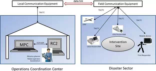
FIGURE 6.
Deployment scenario of ICARUS C2I for SAR operations close to the OSOCC (source: ICARUS).
The SAR mission planner observes the progress of the mission using the MPCS and updates the mission plans. The mission plans are provided to the RC2 system, which the robot operator uses to issue commands and monitor the progress of the robots. In each disaster zone, one or more first responders can carry a mobile device which executes the mobile application. The mobile devices will provide mission-specific data to the robot operator who then uses the information to coordinate the robots. Frequent information exchange is foreseen between the robot operator and the SAR mission planner.
The aim of this scenario is to provide a C2I system that can cater to the needs of a range of disaster situations, thus providing flexibility and extensibility. When a disaster scenario covers a large area or when the disaster sectors are located at distances greater than 3 Km, it might not be feasible for the robot operator to be located at the OSOCC. The reason for this is that the latency in communication will affect the ability to perform time-critical operations with the robots.
In the distributed command and control scenario, the MPCS is located at the OSOCC and is used by the SAR mission planner to generate a mission plan. The RC2 receives at predetermined frequencies mission updates from the MPCS. The robot operator then executes the mission plan by deploying the ICARUS robots at the intervention site. In this distributed concept, multiple RC2 systems can be deployed, each servicing a unique disaster zone. In each disaster zone, one or more first responders can carry a mobile device which executes the mobile application. The scenario is depicted in Figure 7.
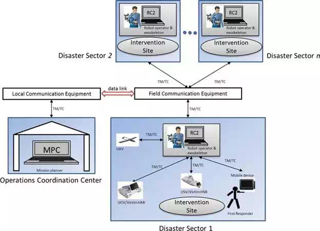
FIGURE 7.
Distributed scenario for SAR operations performed at different sectors (source: ICARUS).
The distributed command and control scenario uses a hierarchical approach for data exchange. The MPCS coordinates and serves as the data server for all RC2 systems, and similarly the RC2 serves as the data coordinator for the mobile devices and the robot-victim HMI, along with hosting the robot platform-specific data.
C2I system architecture
DEPLOYMENT ARCHITECTURE
The main subsystems of the C2I were identified earlier in Section 2.3 where preliminary descriptions of the features of these systems were provided. Figure 8 presents the deployment architecture of the interconnected C2I subsystems. The MPCS is a stand-alone software application that will run on a Windows or Linux workstation located at the OSOCC. It will use Ethernet (IEEE 802.3) or Wireless LAN (IEEE 802.11b/g/n) to share data between the various RC2 systems deployed in the field. The SAR mission planner located at the OSOCC updates the latest crisis data on the MPCS and generates a mission plan for a given sector or sectors. Mission plans and crisis data are distributed to the various RC2 systems via a distributed geospatial information systems (GISs). The MPCS will also have a continuously open link with one or more RC2 systems to send and receive data.
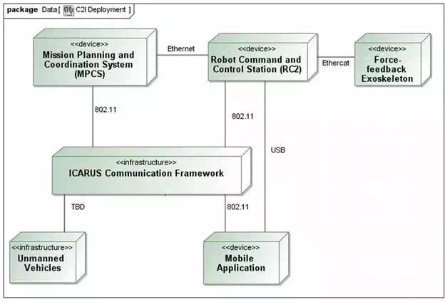
FIGURE 8.
Deployment architecture of C2I subsystems (source: ICARUS).
The RC2 application will be executed on a ruggedized laptop designed for outdoor use, keeping in line with the user requirements for non-LOS and LOS (Line of Sight) robot tele-control. One of its main purposes is to synchronize mission plans and crisis data relevant to the sector it is designated for, with the MPCS. It is foreseen that the RC2 could be located at the OSOCC, alongside the MPCS or in a remote mode, where it links to the MPCS via the ICARUS communication framework. The RC2 pushes knowledge of the sector’s mission progress to the MPCS. The RC2 hosts data critical for the operation of the following hardware: (1) ICARUS robots, (2) the exoskeleton and (3) mobile devices in the field. One of the primary aims of the RC2 is to provide robot operator with intuitive tools to command and control multiple, heterogeneous robots. In addition, it allows first responders with mobile devices to receive the latest mission updates and sectors maps.
Using a mobile device, first responders can push and pull messages, photos and position information over the network to the RC2. All mobile devices will connect via a Transmission Control Protocol (TCP) link (wireless) to the RC2 system. The exoskeleton interfaces with the RC2 using an EtherCAT interface, providing high-fidelity haptic rendering and manipulation capabilities for robotic arm control. The RC2 provides the visual interfaces for visualization of robotic arm movement. In the C2I architecture, robot manipulation, control and sensor data handling are restricted to the RC2.
FUNCTIONAL SOFTWARE COMPONENTS
The MPCS and RC2 are designed to have a distributed architecture where different components (processes) have control and data interfaces. The robot operating system (ROS) middleware has been chosen to implement the C2I components. The motivations behind the adoption of a distributed framework like ROS are the following:
● To maximize the reusability of available robot sensor visualizations, sensor fusion and control algorithms.
● To adopt a standard framework used extensively on robotic platforms.
● This approach is coherent for rapid integration of the C2I with diverse robotic platforms in different deployment scenarios and provides a flexible approach in comparison with contemporary solutions. Existing robot command and control centres are either coupled to a specific robot platform or fixed to a specific SAR deployment scenario.
● Different modules can be developed separately by partners adhering to the ROS architecture and integrated easily within the C2I system.
● ROS defines standard message types for commonly used robot sensor data such as images, inertial measurements, GPS, odometry, etc. for communicating between nodes. Thus, separate data structures need not be explicitly defined for integrating different components.
The MPCS and RC2 user interfaces enable the SAR mission controller to maintain a common operational picture (COP) and manage the execution, coordination and planning of the SAR operation. In Figure 9, different ROS components of the RC2 system have been illustrated at a high level using the ROS framework. A high-level description of each component will be given in the following subsections.
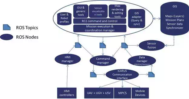
FIGURE 9.
RC2 subsystem components (source: ICARUS).
The MPCS gathers functionalities allowing the specification and management of missions during their execution at the OSOCC level. Figure 10 describes components supporting the assembly analysis of data collected from the mission sections [a.k.a. common operational picture (COP)], the visualization/rendering of these data by users, the specification of mission objectives relying on these data and the planning of mission tasks based on specified objectives and high-level monitoring of mission execution. The MPCS is primarily connected to the SAR first responders—essentially embodied as RC2s. Some of the major components are described below:
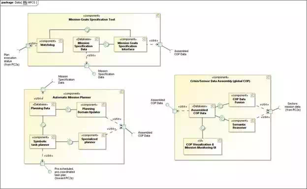
FIGURE 10.
MPCS subcomponents and their interfaces (source: ICARUS).
Mission goals specification tool: This component gathers functions required to specify mission goals. It gathers the main components of the mission goals specification interface, offering dedicated tools for goals definition, a mission specification database where the mission goals are stored and a watchdog monitoring the evolution of the mission execution. Live mission data material, under all available forms: images, various measurements, symbolic and abstract representations, streaming (visual and/or aural), etc.
Watchdog: The watchdog monitors the evolution of the mission execution, possible issues in plan being executed and needs for, e.g. constraints relaxation. The watchdog provides notification of potential issues to the users, so that actions can be taken to update the mission goals accordingly.
Mission goals specification interface: Provides the primitives for ICARUS mission goals identification, such as inspection of a zone, surveillance of a zone, request of perception with certain modalities (e.g. panoramic view) from a given location, etc. Constraints can in addition be specified, such as time extent, robotic platform preferences, human team composition or preferences, etc.
Mission specification data: GIS database storing mission specification data as provided from the mission goals specification interface.
Automatic mission planner: This is a central component that is capable to turn the high-level mission objectives into RC2-level executable task details, which are both pre-coordinated and prescheduled. This means that resulting data are ready for execution while having flexibility in the plan expression (time flexibility, through timelines). It consists essentially of a planning problem builder subcomponent, a symbolic task planner engine and a set of specialized planners supporting the main symbolic planner.
Planning domain updater: The planning domain updater’s main duty is to maintain the symbolic representation of the ‘word’, i.e. the environment and actors, while events and changes occur.
Planning data: GIS database storing the expression of planning domain and problems, accordingly providing material to the symbolic task planner as required.
Symbolic task planner: The symbolic task planner is a major component of the MPCS. This planning engine takes planning data material as input and generates symbolic task plans in which execution (by robots and/or human team) should allow reaching related mission goals.
Specialized planners: The specialized planners are a set of tools with dedicated functions for computing the cost (and possibly modalities), with a set of robot(s) along with the related agent(s) and environment model, to perform particular tasks, e.g. surveillance, inspection, perception making, navigation to a given location, etc. Algorithms used with the specialized planners should allow near-real-time computation, in order to minimize the time required for generating plans with the symbolic planner.
Crisis/sensor data assembly (Global COP): This deals with the gathering, processing, assembling and providing interfaces for live mission information (as provided by the RC2s)—maintaining a consistent overall picture.
COP data fusion: This component will collate live mission information from the different RC2 systems deployed in the field and store it in the assembled COP database for its later access by the mission specification tool and SAR mission planner. This information also gets displayed in the UI. The COP data fusion processes data related to the mission progress and associated events.
Semantic reasoner: This analyses and generates semantic information/knowledge from the mission information provided by the RC2s. The main source of data is sensor information from the robots and GIS (data stored in database). Reasoner analyses the data and creates semantic model of the environment. The model may be represented in multiple forms: 2D/3D semantic map, enhanced sensor data, enhanced GIS maps, etc. The reasoner will compute steps within a maximum of 10 s.
Assembled COP data: This assembles classical and semantic data into a global COP data source that can be exploited by all other MPCS components as required and that is also used to support user’s decision-making (through the user interface). The system will decide which version of semantic information to use: simplified or full.
COP visualization and monitoring UI: Main visualization and monitoring interface for the MPCS. This provides all needed interfaces for the user, as far as mission monitoring is required.
A UML component diagram provided in Figure 11 describes the RC2 software architecture.
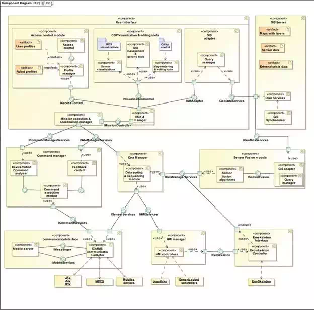
FIGURE 11.
RC2 subcomponents and their interfaces (source: ICARUS).
User profiles: SAR first responders have designated SAR mission planners from LEMA. Authorized SAR mission coordinators are the MPCS and RC2 administrators. An administrator should also have the capability to add new users to access this system. Thus, an access control mechanism is needed to ensure that only authorized users can use this system. This subcomponent of the user interface uses a local encrypted repository to store and retrieve the user profiles primarily consisting of C2I system access control information. A graphical user interface will be provided to (i) login to the C2I, (ii) add or create a new user, (iii) delete an existing user and (iv) modify the access information of an existing user (e.g. change of password).
Access control module: The access control module provides access control functionality in the RC2 system. Its aim is to use a SQLite database to manage user profiles and provide a GUI for users to log in and log out. Although not an explicit user requirement in the project, basic security features will be implemented via this module.
Robot profiles: The C2I system is used to communicate and control heterogeneous robot platforms such as UAVs, UGVs and USVs, with each system having different capabilities (e.g. autonomous, semi-autonomous and tele-operated), sensors and platform-specific concepts. This information is important for planning a mission based on robot capabilities and types of commands that it can execute. Robot profiles will be gathered from all the robotic platforms deployed within the ICARUS framework and stored in a local repository. A generic ROS message schema has been designed (refer to ‘Interoperability’ section) to dynamically include the features of each robot into the RC2.
Mission execution and coordination manager: This module is specific to the RC2 with a functionality that is a subset of the Global SAR mission coordinator. It has a local view of the SAR mission related to its assigned sector unlike the MPCS, which has a global view of the SAR mission distributed among sectors. It is responsible for triggering the exchange of information between robotic platforms and SAR team members for a coordinated approach to address the mission.
GIS adapter: The GIS adapter is responsible for creating queries to the local GIS repository based on requests from the map and robot sensor visualizations. This module receives a set of query parameters, and an appropriate query string will be generated to extract information from the GIS. The GIS provides multiple interfaces for accessing data such as the open geospatial consortium (OGC) standard interface (for maps) and a set of legacy services, to access dynamically generated geo-resources (geo-tagged sensor data and images).
Map rendering and editing tools: A central map widget will be developed to render global base maps using open street maps (OSM) from a local GIS repository. This widget can display aerial maps (captured by unmanned aerial vehicles) overlaid on the base maps. The map will be used to display the locations of unmanned systems and human SAR personnel based on their GPS locations. Tools will be developed for adding waypoints on the map, sectoring areas by drawing polygons, taking geo-tagged notes, tagging images, setting transparencies for different layers and enabling/disabling path tracking for human and unmanned SAR entities.
Data manager: The ICARUS communication framework provides a link for receiving data from SAR teams and unmanned platforms. This data is encapsulated in the format defined by the JAUS standard data formats. Message generating modules on deployed ICARUS systems publish geo-tagged sensor data, crisis map updates and other types of data such as voice and images. The data manager at the C2I side is responsible for:
● Decoding or de-serializing sensor data received from robots within the ICARUS communication framework.
● Decoding commands and its associated data, sent between the MPCS and RC2.
● Identifying nodes in the C2I system which can use different types of data.
● Forwarding/channelling de-serialized data across appropriate topics.
This component will provide the main software interface for access to robot sensor data and GIS data. The data manager will provide services for clients to access online as well as offline sensor data. For online sensor data, clients will be able to access RGB (mono and stereo), IR and depth map data available on a specific robot. The sensor manager provides a gateway between crisis data updates received from the MPCS and the geospatial/sensor record database. Live sensor data will be routed to the sensor fusion algorithm component.
Sensor visualization and associated tools: Robot sensor visualizations from the RVIZ-ROS framework are reused and adapted for ICARUS robotic platforms. Existing visualization plugins for 3D point clouds, robot models, grid maps, camera view, etc. will be enhanced with features to improve usability and clarity for the C2I operator. Custom visualization plugins will be developed for robot pose (roll, pitch and yaw), network quality, power status, digital compass, etc. Tools associated with visualizations include 3D image viewpoints, user annotations (points, lines or text), plugin settings, add/remove plugins, etc.
HMI manager: The Human Machine Interface (HMI) manager manages inputs and outputs, from and to HMI devices, respectively. Input devices consist of robot controllers for unmanned systems such as:
● Joysticks
● 3D haptic controllers
● Exoskeleton (joint positions and forces)
● IMU inputs from head-mounted displays (HMDs)
Feedback or outputs from sensors on unmanned can be provided to HMI interfaces capable of rendering them such as:
● Wearable heads-up display (video feeds, robot pose)
● Exoskeleton (haptic force feedback, joint encoder positions)
● Force feedback joysticks
● Calibration of joysticks
The HMI manager in Figure 12 manages bidirectional data flow between HMI devices and unmanned systems and encodes data depending on the device. For example, control inputs for robots and their peripheral actuators (e.g. robotic arm mounted on a UGV) need to be scaled or interpreted according to the type of end effector. The HMI manager is essentially a ROS node that subscribes to other ROS nodes driving their respective HMI devices. The following diagram illustrates the high-level distribution of the HMI manager with respect to its child nodes.
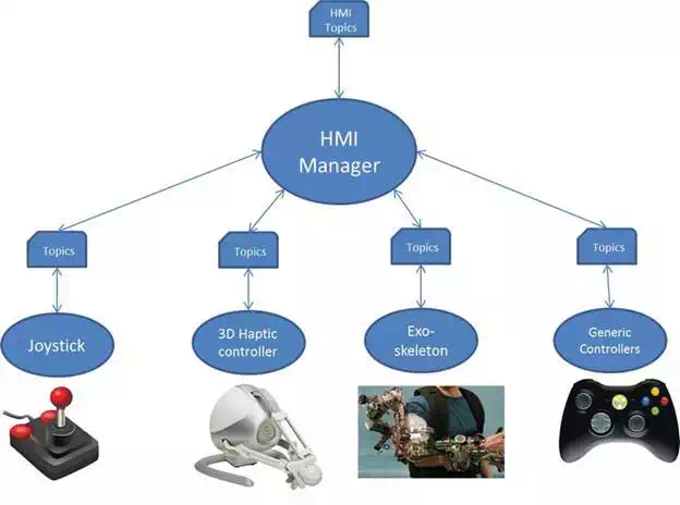
FIGURE 12.
HMI Manger node and its child ROS nodes (source: ICARUS).
Platform command manager: This component provides and manages the software interfaces between the robots and the C2I. The platform command manager sequences the commands (scripts, waypoints) through the communication manager to the robots. In its current form, this component is an abstraction for interfaces that receive robot-specific commands. The component handles temporal sequencing of the command data using signals fed forward by the mission execution controller.
Command analyser: The coordinated command generator is a component that will manage cooperative behaviour between pairs of robots such as a UAV and UGV or a UAV and USV. Its purpose is to receive mission-specific coordinated task commands from the user via the command and control UI. It uses instances of the platform command manager to coordinate command execution between a pair of unmanned platforms. This includes data synchronization between robots.
Mission execution controller: The mission execution controller is primarily responsible for differential control of the progress of the unmanned platforms with respect to the mission plans provided at the UI. The mission execution controller evaluates the robot’s state against the mission plan and provides the command and control UI with appropriate feedback mechanisms. The mission execution controller is responsible for maintaining the current mission state and sequencing the subsequent, desired states based on the mission plans provided by the MPCS. Excessive deviations from the mission plan or state requires replanning, and this results in a new mission plan request to the MPCS.
Command and control UI: This UI provides the primary front end for user which includes all the tools necessary to monitor and control the robots . Several information-rich sensors mounted on the robots such as ToF, RGB, IR and stereo cameras will be used to improve the performance in search and rescue tasks. The command and control UI provides the main map/crisis data viewing capabilities to enhance the robot operator’s situational awareness of the SAR mission including progress of robots and first responders in the field. The UI presents the data generated by the mission execution controller to determine the mission-level progress of the robotic platforms. The UI will provide commanding capabilities for the UAVs, UGVs and USVs (abstracted by the level of autonomy). The commanding capabilities provided by the UI will include joystick inputs, spatial waypoints and mission-level commands (if supported by the platform). The UI interfaces with the platform command manager to deliver the commands to the robotic platforms. The command and control UI will rely primarily on touchscreen, keyboard and joystick inputs. An additional input device in the form of the exoskeleton will also provide a subset of command generation capabilities for the robotic arms mounted on the UGVs. The mission plans are GIS layers describing the sequence of tasks that must be performed for a given mission scenario. These plans are accessible by the mission execution controller. The mission plans are outputs of the MCPS system and are when available pushed to the RC2 mission plan database through the MPCS synchronizer.
Sensor fusion algorithms: This component will provide a set of algorithms for multi-robot multi-sensor data fusion. The command and control module can receive raw and on-board preprocessed data from the different robots. Under certain conditions and when the command and control module requests so, the sensor fusion algorithms are responsible to post-process this data provided by the data manager and translate it into a consistent representation usable by the rest of the components. The sensor fusion algorithms can act at different abstraction levels: robot states (i.e. health, navigation state), imagery, maps, features and landmarks.
GIS server and synchronizer: This component is the repository where the system will store all geospatial data gathered for the different components of the system. This component allows transforming the geospatial information storage in the system to the appropriate format allowing map viewers to compose this information in a final map. This component uses different OGC services [web map service (WMS), web feature service (WFS), web feature service—transactional (WFS-T)] for synchronization (upload and update) between the information storage in the system and information gathered from the mobile devices at the RC2s and the between the MPCS and RC2s.
Mobile device server: The field device manager handles the data flow from the various mobile devices in the field. Its purpose is to handle and route text message flows and map updates and latest crisis data between the RC2 and mobile devices in the field. It will remain the central system to pull location data from the mobile devices, i.e. device GPS position. The component will use XMPP/Jabber standards for instant messaging support. In summary, the field device manager will ensure connectivity between the field devices and the GIS on the MPCS and RC2.
Communication interface: The communication interface manager is the middleware responsible for managing all data communications between the various actors in the crisis area (R2C, MPCS, Robots, etc.). The communication manager will implement data streams that provides access to the different data uplink and downlink to robots, ensuring that link quality and loss handling are adequately covered according to the requirements necessary for the application (sensors, video, etc.). The application programming interface (API) offers interfaces to encapsulate the traffic requested by applications within ICARUS communications framework.
This module, in combination with the C2I user interface, has been designed to help the operator to get a clear overview of the emergency situation. The following list shows a simplified concept of operations workflow from the initial reconnaissance flight to the development of the mission (also depicted in the figure below). In Figure 13, we can see the different functionalities describing the data fusion module as follows:
1. From the MPCS, the initial high-altitude flight with the long-endurance UAV is launched.
2. This gathers an initial set of high-altitude (and presumably low accuracy) images that are used in data fusion to create the initial map of the area.
3. This map is used to show the operator the current state of the area of interest.
4. In parallel, this map image is parsed through a surface contextualization (characterization) that proposes sections between concepts such as forest, water, buildings, roads, etc.
5. The operator, with the help of points (1)–(4), has a general overview of the situation and can manually create sectors that will be distributed through the different RC2.
6. Each RC2 will be given a sector to start the operations, with the initial map done in (2).
7. The operator in RC2 will then ask for higher-accuracy and lower-altitude images on specific areas to update the map with visual images, possible location of victims, 3D structures, GIS updates, etc.
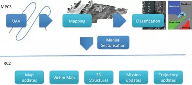
FIGURE 13.
Concept of operations with data fusion functionalities (source: ICARUS).
The specific architecture of this module and its interaction with other modules (namely command and control UI and geospatial database) is illustrated in Figure 14. As general comments, the module will be implemented in C++ with the possibility of integrating ROS in order to ease testing and scenario replay during implementation. In the final version, direct read and write to the database might be the chosen approach to gather the required information to build up the results and storage of the resulting images and GIS updates. The big picture of the data fusion architecture is summarized in the following picture.
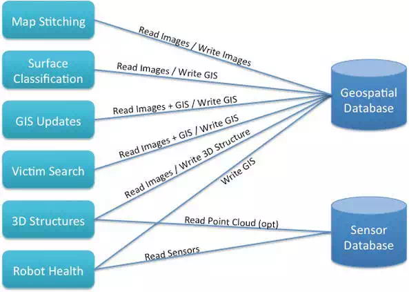
FIGURE 14.
High-level data fusion architecture (source: ICARUS).
A state of the art description along with the proposed approach to develop each functionality (each box in the previous picture) is described in the following subsections.
MAP STITCHING
For this approach, the main key points of the object (image to stitch) will be detected and extracted along with the ones of the map. The surf feature detector and surf descriptor extractor will be used for that step. Other descriptors are being considered depending on the time and quality demands of the end-user. The descriptors will be computed and then matched using the Flann based matcher. Notice that other matchers like the brute force can be used too. Once the matches are computed, they will be used to get the homography function letting us to wrap the object on the same plane as the map and attach them in the same image. After an evaluation of the approach, OpenCV seems to be a good choice for the image computing library.
SURFACE CLASSIFICATION, GIS UPDATES AND VICTIM SEARCH
In this step, the main objective is to extract as much information as possible from the UAV’s images. The type of terrain is going to be computed using a grid of surf descriptors applying a threshold. This segmentation will suffer two steps of optimization: first of all, small segments will be connected or erased; secondly, the regions will try to grow and see if colliding terrain can be added. If so, a texture and colour classification process will decide which type of terrain the conflict region is most probably in.
MAP SEGMENTATION
The classifier proposed is support vector machine (SVM), which uses learning algorithms that analyse data and recognize patterns. During the training algorithm, SVM builds a model that assigns new samples into one region or other, making it a non-probabilistic binary linear classifier. An SVM model is a representation of the samples as points in space, mapped so that the samples of the separate regions are divided by a clear gap that is as wide as possible. New samples are mapped into the same space and predicted to belong to a region based on which side of the gap they fall on. The classification is based on colour image, where each pixel of the map (samples) is classified by its value of hue, saturation and value (HSV). Based on that premise, the red, green and blue (RGB) colour of the original map is converted to HSV. Hue defines the shade, which means the location in the colour spectrum (the neutral colour) that is determined by the reflective property of the object surfaces and it is relatively stable. Saturation describes how pure the hue is with respect to a white reference. Value defines the brightness, amount of light that is coming from the colour. These two depend on occlusion variation and the shape of the object.
The RGB colour of the map not only depends on the camera configuration (focus, exposure, lens, etc.) but also on the weather conditions (i.e. Sun elevation and clouds that may vary the brightness). Based on these premises, the classifier needs to be trained with the desired regions (vegetation, land, water, etc.) what is known as ground truths; the user must determine a small but representative set of pixels for each region. At this point, the classifier builds a model that may be used to classify the maps.
The SVM prediction is implemented in a ROS service; when the service is called, the original map is taken from a specified path of the hard disk. The map is divided in several areas; the total amount of areas is the same as cores have the computer where the service is called. A multithread is launch to classify (predict) the entire map minimizing the computational time. The prediction process takes normally around 2 minutes. Finally, the segmented map is saved in another specific path of the hard disk. The entire procedure is summarized in the following flow chart (Figure 15):
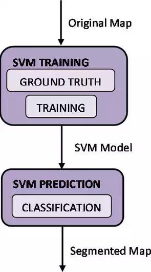
FIGURE 15.
Map segmentation box diagram (source: ICARUS).
MAP GENERATION
The objective of this module is the creation of a 2D aerial map in near real time. This map is produced from the images provided by the different aerial robots, and its main purpose is to furnish the operator with a quick update on the conditions of a particular patch of terrain. Additional maps can also be produced in the post-processing step such as a digital elevation model (DEM) and a 3D structure (in form of point cloud or mesh).
First of all, the key points are detected and extracted for every image and stored in their respective keyfile. As soon as an image keyfile is ready, its key points are matched with the ones of the previous images. During this stage an optimization using the GPS coordinates allows us to reduce the number of image comparisons by more than a 90%. This fact also allows us, most of the times, to run the matching process in near real time. At the end of the matching, we use the matching table to perform a bundle adjustment and retrieve a 3D sparse point cloud. Once the 3D point cloud is ready, we use it to create a 2D projection or a 3D render depending on the user demand. This pipeline is depicted in Figure 16.
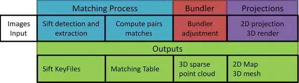
FIGURE 16.
Map generation box diagram (source: ICARUS).
Mission planner is a stand-alone module of the C2I designed to be a support tool during the action-planning phase [30]. The planner facilitates the preparation of a mission plan for each team and sector. Data form the MPCS database is used for this purpose. Mission planner has two main elements: symbolic planner and specialized planners.
SYMBOLIC PLANNER
The symbolic planner (or ‘task planner’), Figure 17, is the core component of the toolset supporting the ICARUS mission planning. It is part of the MPCS and is therefore running in the OSOCC. The purpose of the symbolic planner is to generate detailed action plans for the ICARUS’ robots, accounting for the mission context and available information on mission progress. The symbolic planner, as its name means, takes as input (1) a symbolic representation of the knowledge about the mission (environment, mission context, available resources, various constraints including temporal ones, etc.) and (2) high-level mission objectives (goals) expression. The planner generates one (or several) task plan(s) that can be handled at the RC2 level for a coordinated execution by the different robots (relying on the RC2’s mission execution and control manager). The symbolic planner relies on a LISP implementation of the Shop2 HTN planning engine, exploiting a hierarchical definition of the planning domain. As per this paradigm, high-level methods are decomposed into lower-level tasks (either methods or operators—in blue, in the pictures below) when method’s preconditions are satisfied, until the planner reaches primitive tasks. We moreover introduce in the planning scheme time considerations thanks to an encoding of the domain exploiting the so-called multi-timeline processing (MTL). This scheme allows expressing durative and concurrent actions and allows effectively accounting for time constraints.
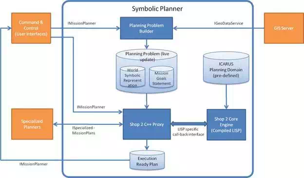
FIGURE 17.
Symbolic planner architecture (source: ICARUS).
As part of the planning scheme, we introduce specific operators that allow performing on-the-fly (i.e. during the planning process) requests to the specialized planners—this deals, e.g. with estimation of time or energy consumption for navigation between two points in the environment or for the identification of best suited location to perform perception. Results from queries to the specialized planners are considered in the generated task plan, accordingly. We summarize in this section the components and their connections as part of the symbolic planner, as it is implemented for the MPCS. The symbolic planner basically consists of the three following components:
1. The Shop 2 Core Engine is the planning engine, which is based on the Open Source Shop 2 planner (LISP implementation). It takes the ICARUS planning domain and the live update of the planning problem as inputs that consist of (i) the symbolic representation of the world and (ii) the mission goals statement.
2. The world symbolic representation and the mission goals statement are formatted in the proper planning formalism through the planning problem builder (C++ implementation). This component requests information about the actors and ongoing mission situation and maps data that are relevant for the planning process. This includes models of the available resources (robot, personnel, etc.) and status of these resources (power left, availability, etc.) All this information is obtained from the GIS Server. The mission goals statements are obtained from the command and control system, with a dedicated user interface for mission definition.
3. As a mean to interface conveniently with the Shop 2 Core Engine (which, as mentioned before, is LISP based), a Shop 2 C++ proxy allows interfacing in a conventional manner with components that interact or may have to interact with the planning process—mainly (i) the specialized planners that supports the symbolic planner during the planning process with specific planning capabilities requiring, e.g. semantic or motion/path planning-related evaluation, and (ii) the command and control interface, from where the planning process is handled (e.g. starting new planning cycle, modifying planning policy or parameters, etc.). This proxy should also turn rough task plans, as generated in the Shop 2 planner formalism, into an execution-ready plan that complies with RC2 formalism expectations (through the command and control interfaces) and that the RC2 can therefore directly exploit.
SPECIALIZED PLANNER
Specialized planners form a module that responds to requests from the symbolic planner. The requests concern detail, computation heavy problems such as path planning, proper positioning, etc. Specialized planners use a semantic model of the environment (SME) constructed by a subsystem of the planners based on the GIS and data gathered by the unmanned platforms.
The specialized planner module consists of two main parts: semantic environment constructor and query processor. The semantic creator gathers data from GIS server and sensor fusion feed and analyses them to create the SME representation of a given area. The creator performs basic concept recognition according to a defined ontology. Query processor works as a server. The client sends a query, which defines the task and provides needed parameters. The processor then tries to formulate a response based on the SME model and given parameters. The query response is then sent to the client. The planners use specialized technologies to improve computation time and SME creation:
● NVidia PhysX: This popular physics engine is used to simulate the SME. It allows for simulating concepts in form of static and dynamic entities and provides tools for automatic event catching and handling. The events are used to follow the relations between concepts.
● NVidia CUDA: This SDK allows to perform parallel computation on graphical cards. This allows a decrease in computation times for many parallelizable algorithms.
The planners are being designed to work with a set of standards to provide consistency and compatibility with other C2I components:
● Qualitative spatio-temporal representation and reasoning (QSTRR) framework. It provides the base for the SME creation defining basic ontology.
● ROS: The module of the mission planner will be prepared as nodes of the ROS framework. This will provide means for easy communication with the rest of the C2I.
● QT: A popular set of libraries for creating GUI and application backend logic. The program will use QT classes for internal communication.
● OpenCV: Libraries for machine vision.
An important standardization element of the planners is ontology. It defines the concepts of the semantic model, relations between them and rules for maintaining integrity of the model. The next paragraph will show a short overview of the ontology.
Specialized planners consist of modules shown in Figure 18:
● Data reception and preparation module: This module is responsible for receiving the input data and preparing it to be used for SME creation. In the process, the data is grouped into packages. Each package contains information about single sector. Additionally, the data is being preprocessed, for example, 3D point clouds are filtered and normal vectors are computed for each point.
● Semantic model creation and upgrade module: This module is responsible for creating the semantic model of environment and distributing it to other modules. Input data is processed to extract semantic information and transformed into the ontology-compatible format.
● Semantic model modification module: This module receives the queries from the symbolic mission planner and creates instances of the semantic model based on the received parameters. This process includes changing practicability of area considering robot type, including the sensor model.
● Main reasoner: This is the main reasoning engine for the specialized mission planner. The base for the module is PhysX-based simulation environment. The module creates a hypothesis space and then tests the hypothesis by a set of conditions. The hypotheses that are considered best are sent as an output.
● Secondary reasoner: Secondary mission planner reasoner is a module that answers special inner queries asked by the main reasoner. The advantage of this module is that it uses CUDA-based algorithms which allow for reducing the computation times.
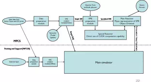
FIGURE 18.
Architecture of the specialized planners (source: ICARUS).
OVERVIEW
The MPCS GIS repository is the main repository within ICARUS system, and it is typically located within the OSOCC infrastructure. Before the deployment of ICARUS system in the catastrophe area, the MPCS GIS repository is loaded with all cartography, imagery and thematic datasets related to that area, which will be used as input by the users (e.g. visualization of maps in the main workstation operated by the operator on duty) and subsystems connected to it (e.g. mission planner) to carry out their assigned tasks (e.g. locate with the support of robots, victims nearby crumbled buildings). The access and management of the information in the GIS repository are done through OGC standards and compliant http services by using POST and GET requests.
Apart from the local datasets stored within it once the system has been deployed, additional sources of information that might be of interest/support for the SAR operations through the access to external mapping services and information repositories (e.g. GDACS), providing thus complementary and useful information that can be used to improve ICARUS operations on the field. To that end, the MPCS provides a component in charge of dynamically accessing to these external sources of information and adapting it to ICARUS GIS repository internal data model based on humanitarian data model (HDM). In order to accomplish this, the component defines for each external service or repository a data model mapping, which describes how to transform the original data source into ICARUS internal data model.
In turn, at the beginning of each SAR mission, different geographical subsets of the MPCS GIS repository are copied locally to the GIS repositories within the different RC2 systems operated by the SAR teams in different areas. At the end of the day, the updated/modified information within the RC2 GIS repositories is synchronized and merged with the main GIS repository in the MPCS.
The aim of the RC2 GIS component is to store all the necessary information that the SAR personnel operating the RC2 component might need in order to accomplish their assigned tasks. In this regard, the RC2 GIS can be seen as a reduced version of the MPCS GIS, hosting a subset of the geographical layers and information contained in the MPCS GIS repository. During a mission, the RC2 GIS will update locally the original information by modifying its contents (e.g. the location of a victim) or adding additional resources (e.g. sensor information retrieved from the robots and stored in the RC2 repository, mobile phone images, etc.). At the end of the day, the local RC2 GIS repositories will be merged and synchronized with the MPCS GIS repository to update the central repository and have a homogeneous and coherent situation status for planning future missions. RC2 GIS repository will also store the mission plans sent by the MPCS, as well as any modifications that can be made locally if necessary.
Other important differences with the MPCS GIS are:
● RC2 GIS has no direct access to the external repositories, but if necessary it could access the retrieved data through the HTTP interfaces available in the MPCS GIS.
● Sensor data from robots (except for the case of the UAVS) are stored in the RC2 GIS repositories and synchronized to the MPCS GIS (due to the bandwidth constrains for transferring large amounts of data).
The aim of the mobile device directly connects to the GIS server hosted on the RC2 via Wi-Fi and cache important WMS and WFS layers for offline operations, thus supporting the personnel working on the field over the course of the mission execution. Due to the inherent limitations in the storage and computational capacity of this type of devices as well as with the related network bandwidth limitations which prevent from transferring large amounts of information between the RC2 or MPCS and the mobile devices, the approach followed by it differs slightly. The mobile device will store a basic set of layers, allowing the user to work offline and carry out typical operations such as updating information (e.g. set a building as visited, changing the location of victim to a new GPS coordinate, etc.) or creating new resources by taking geo-tagged pictures with the mobile device camera. Once the user enters an area with network coverage (e.g. 3G or Wi-Fi), the mobile device GIS automatically will try to contact the RC2 GIS services to retrieve possible updated layers (e.g. using the WMS or WFS) and then update accordingly its local cache. In addition to the GIS repository, the mobile device GIS will also provide a user interface—based on HTML5 and JS technologies—that supports the user with the necessary functionality to manage and interact with the locally stored information. Typical operations available are (i) zoom in and out; (ii) pan; (iii) draw polygons and associated information to it; (iv) take geo-tagged images with the camera, notes, points of interest, etc.; (v) send and receive text messages; and (vi) connect and retrieve/provide information from RC2 and MPCS services (i.e. OGC and ICARUS legacy RESTful services).
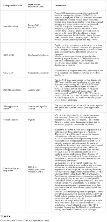
TECHNOLOGIES AND STANDARDS
Table 1 presents the selected open source implementations for each of the databases and services mentioned above.
GIS ARCHITECTURES FOR MPCS AND RC2
The aim of the GIS database component is to serve as a repository for storing, accessing and manipulating all the required geographical information used or generated in the context of ICARUS operations, thus a central part of ICARUS architecture. In this sense, several components and subsystems rely on the information it contains, such as the mission planner, the data fusion algorithms or the teams deployed on the field, which might require cartographic and aerial layers of the area where they are working in terms of maps or alphanumeric information. The GIS database is an integral part of the MPCS and RC2 subsystems.
It provides the same core functionalities for both with some specific differences regarding the requirements of those two subsystems. As mentioned before, the GIS repository will store different geospatial layers, maps and any other information geospatially tagged piece of information by means of:
● Files (typically for raster images such as GeoTIFF, JPEG, point clouds, ESRI shapefiles, etc.).
● Relational spatial database (typically for vectorial and alphanumeric data).
● HTTP RESTful services compliant (in most cases) with OGC standard interfaces and operations in order to make it interoperable with other external services and subsystems (e.g. mobile device used by field teams accessing to the latest aerial images located in the RC2 GIS repository through the OGC WMS service). Using the OGC standard interfaces, a set of supplementary operations provide additional functionalities not covered directly by these standards, such as the upload and management of dynamically generated geo-resources to the ICARUS GIS repository (e.g. sensor data, mobile device images, geo-referenced text messages, etc.).
Currently the architecture in Figure 19 includes some geospatial information systems (GIS) standard services based on open geospatial consortium (OGC):
● Web map service (WMS): It serves geo-referenced map images, and it supports pyramidal raster; an image pyramid is several layers of an image rendered at various image sizes, to be shown at different zoom levels. Main operations performed by the service are:
○ GetCapabilities
○ GetMap
○ GetFeatureInfo
● Web feature service-transactional (WFS-T): It is capable of serving features, and it allows creation, deletion and update of features. Main operations performed by the service are:
○ GetCapabilities
○ DescribeFeatureType
○ GetFeature
○ Transaction (update, insert, delete, edit)
● Styling: The maps from the WFS service have customized styling; this is done with styled layer descriptor (SLD) technology for all open street map data. The rest of WFS data depends on the client side.
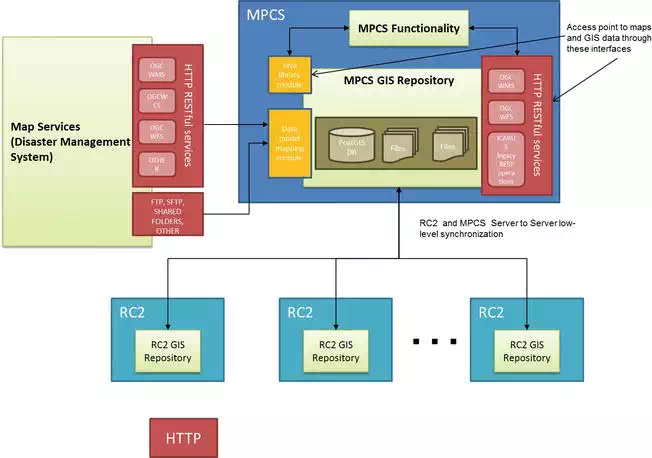
FIGURE 19.
MPCS GIS high-level architecture (source: ICARUS).
The software components in Figure 20 include the deployment and configuration of two main components in addition to PostgreSQL database:
● Tomcat 7 is a servlet container supporting 52 North SOS and GeoServer as well as GDACS services. The main components deployed on it are:
○ GeoServer: This is a java-based service deployed under Tomcat 7. Its purpose is to act as WFS-T and WMS. Its main advantage is that it provides transactional operations over the vectorial data within the database.
○ MapServer: This is a C-based service deployed under Apache 2 as a CGI, and its capabilities are to work as WFS to provide different output format responses apart from Geographic Markup Language (GML); indeed this service response could be a CSV or a JSON file. As WMS, it supports Enhanced Compression Wavelet (ECW) raster format.
● Apache 2 web server has been configured to provide Common Gateway Interface (CGI) support to make MapServer working, and it is also the main entrance to the server through port 80 and redirects all traffic to Tomcat 7.
○ The Apache 2 web server oversees publishing sensor images stored in the system. This server has installed Python library, and it is configured to support a Python-based proxy to allow usual third-party javascript requests.
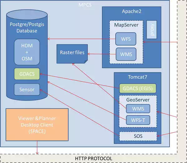
FIGURE 20.
GIS software components (source: ICARUS).
There is a Postgre databases already installed and extended with PostGIS to support all the geospatial functionality. The ICARUS schema is composed of:
● Open street map (OSM) tables, storing vectorial data for Lisbon, Moia and Marche-en-Famenne. For each scenario, there are three tables (polygons, points and lines). Those tables have been expanded with several columns to match humanitarian data model (HDM) schema.
● Internal ICARUS tables to keep track of mission, its zones and sectors, as well as teams and its members (humans or robots) as well as their positions through the waypoints table. There are structures and victims that could be located, since, apart from specific data, all these tables have a geometry field to be able to geospatially locate each occurrence.
EXTERNAL CRISIS DATA
The purpose of integrating map layers from external suppliers is to have a greater amount of information, that is accurate and up to date. The integration of information from other crisis management systems will permit to release systems and other resources partially of workload, without losing functionality. In certain cases, external data sources will allow comparing external information with GIS internal information, obtaining more detailed information. Comparing internal information makes it possible to obtain a more complete picture of the situation.
GLOBAL DISASTER ALERT AND COORDINATION SYSTEM (GDACS)
The global disaster alert and coordination system (GDACS) provides near-real-time alerts about natural disasters around the world and tools to facilitate response coordination, including media monitoring, map catalogues and virtual on-site operations coordination centre. GDACS (Figure 21) is a web-based platform that combines existing web-based disaster information management systems with the aim to alert the international community in case of major sudden-onset disasters and to facilitate the coordination of international response during the relief phase of the disaster.
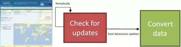
FIGURE 21.
(i) Homepage of GDACS, http://www.gdacs.org/. (ii) Periodical update of GIS with data (source: ICARUS).
GDACS provides the ‘virtual OSOCC’ (www.gdacs.org/virtualOSOCC) to coordinate international response. The virtual OSOCC is restricted (password protected) to disaster managers worldwide.
● GDACS information service providers are organizations or services that provide or manage disaster information. These include:
● European Commission Joint Research Centre: Automatic alerts and impact estimations
● OCHA/virtual OSOCC: Web-based platform for real-time information exchange among disaster managers
● UNOSAT: Provision and coordination of map and satellite image products
● OCHA/ReliefWeb: Repositories of damage maps and impact analyses, which in the aftermath of a disaster are made available through an RSS-based catalogue, which is available in GDACS
GDACS information service providers share information and synchronize their systems according to GDACS data coordination standards. These are:
● Extended really simple syndication (RSS) feeds to transfer and integrate information between databases and websites of its users.
● The GLIDE number (www.glidenumber.net) as unique identifier for disasters to link information related to a given disaster.
● Common Alerting Protocol (CAP).
MAPACTION
MapAction is an international NGO that provides maps and other information services to help humanitarian relief organization in field. They are responsible for the data collection and information management and also offer access to mapping information (in paper and digital format).
SOFTWARE ARCHITECTURE
The most important thing is to perform an initial analysis of the generic structure of the GeoRSS that is going to be integrated. It is essential to know the refresh rate of the selected external provider data sources. If the refresh rate is variable, it is needed to define a parameter that sets the time interval in which to check for updates have occurred in the source. GDACS implements a system of email alerts; it might be possible to detect these warnings and proceed to check if there is an update in the data. Subsequently it is necessary to compare the data structure of the original source and see how the information can fit in the data model of the developed system. Consequently, a process responsible for periodically checking for updates in the data sources will be created. If an update has occurred, data will be retrieved. A system based on predefined rules from the previous studies will be developed; retrieved data that has been collected will be converted to the data structure defined in the application.
Stored data are in the following tables in PostgreSQL:
● Gdacsitem: current disaster items (RSS last reading data)
● Gdacsitemhist*: all historical items
● Gdacsresource: resources associated with the item
The most relevant data are collected from the following RSS:
Disaster items:
● Identifiers: unique disaster identifier + episode identifier
● Registration data in our system and item data
● Title of disaster and description
● Alert level and description of the magnitude
● Event type
● Country
● Affected population and victims range
● Position (latitude and longitude): geometry
Item resources:
● Item identifiers and the episode with which it interacts
● Register data in our system
● Title and description
● Resource source
● Link
● File type (image/wms/xml/txt)
RSS reading: RSS reading is done in an ongoing basis. A thread has been built which reads the RSS, and it compares the changes with the last reading existing data. In this way, it only registers new items, and it withdraws those who are not active. The development consists on a JAVA web service that has the ability of configuring the most suitable reading interval.
Files: Associated to items, there are many resources such as documents, images etc. that can be accessed through URLs. The web application that reads the RSS, in addition to store data into the database, stores files (Figure 22) locally of those resources that we are interested in and that may be imported. For instance, a URL of a WMS does not help us and due to this: a configurable white list has been created with those resources extensions in which we are interested.
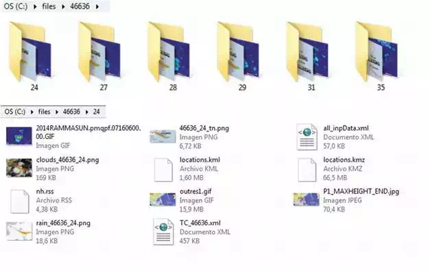
FIGURE 22.
Disaster episode folders and files in each episode stored in file system (source: ICARUS).
Layers and symbolization: Stored data in GIS database as seen in the GDACS-GIS architecture (Figure 23) have the geographic localization of the disaster (lat and long). Both items table as historical items are published through the GeoServer map server. The two published layers are symbolized in the same way as in GDACS website. So as to that, we have a Styled Layer Descriptor (SLD) and an array of icons to represent different states and disaster types. Disaster items are depicted by the value of the field ‘subject’.
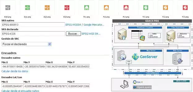
FIGURE 23.
GDACS-GIS architecture (source: ICARUS).
MERGING INTO GIS
By comparing the GeoRSS catalogues of GDACS and MapAction, the latter has a smaller amount of information. Another reason to decide that GDACS is going to be the main external data provider is that it has a clearly predefined structure for the GeoRSS catalogue. This standardized structure will facilitate the automation of the integration of external data into ICARUS data model. GDACS has the following standards to publish information:
● Feeds must be compatible with all RSS and GeoRSS viewers.
● The main GDACS feeds must contain links to all GDACS partner feeds, allowing applications to drill down to more information.
● Model results must be made available as a separate feed. However, key data can be exposed in the main GDACS feed.
● GDACS main feed must contain a minimal set of standard GDACS elements that are available for all disaster types. These must be compatible with CAP for easy transformation:
○ Time (period): from, to and status (forecast, ongoing, ended)
○ Information on whether event is ‘active’
○ Event type
○ Severity: abstract independent of hazard but containing enough information for characterizing the full severity
○ Population in affected area
○ Vulnerability of affected country
○ Alert core/level
○ Severity (CAP)
○ Urgency (CAP)
○ Certainty (CAP)
● An identifier section disambiguates many identifiers.
● A resources section lists all GDACS partner information feeds.
Figure 24 shows the structure of an RSS file served by GDACS. As can be seen, there are a series of tags that define various attributes of the data source (title, description, access level) and finally the resource. In the example the data source is a type WMS.
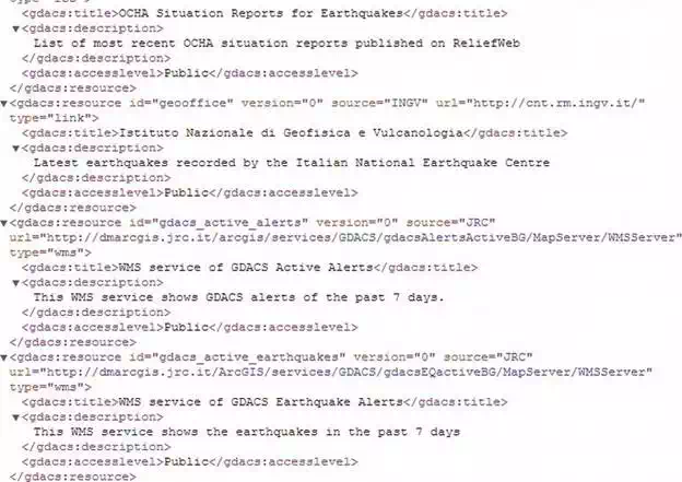
FIGURE 24.
GDACS GeoRSS example, http://www.gdacs.org/XML/RSS.xml (source: ICARUS).
HDM EXTENSIONS FOR ICARUS
This section provides details on how to relate the HDM and the extensions provided above to the relational spatial database used to store and manage these layers. The GIS repository follows the humanitarian data model (HDM)—with additional extensions/adaptations necessary to fulfil ICARUS informational requirements—thus providing a common and interoperable data model shared among all applications and systems within ICARUS that requires geospatial information. This, in addition, has the advantage of allowing the integration of external data sources that comply with HDM as well as offering ICARUS information to external parties. Extensions of the HDM with layers which are of interest for ICARUS purposes are as follows:
Geographical sectorization: Subdividing a geographical area into several sectors is an important feature that the C2I system must have, to support asset organization, mission analysis, decision-making, etc.
Strategic locations: This should be specified in the C2I filters.
Buildings: In catastrophes that happen in land, such as earthquakes, buildings can suffer different degrees of structural damage, from simple cracks in the walls to destruction. In such cases, often individuals become trapped inside buildings, and SAR operatives must enter these buildings in order to rescue the trapped victims. Important temporary sites
Victim recovery operation: Rescuing victims in any disaster scenario is one of the top priorities of any SAR operation and to maximize the efficiency of all the SAR teams on the field, the C2I must employ the necessary tools to ensure that all victims are tracked and assigned to a team.
Human and robot tracking: When SAR operatives are deployed on the field, each of them is assigned to a team. After teams have been formed, their members are then able to cooperate efficiently in rescue missions that are assigned to them.
Mission plans: When a location is identified as either having a possibility or certainty of having victims, a SAR mission is immediately created, associated with a search area and assigned to a SAR Team if one is available.
LOW-LEVEL SYNCHRONIZATION BETWEEN MCPS AND RC2
At the initial moment, both MPCS and RC2 GIS repositories contain the same version of the information. Over time the information in both components is modified locally (e.g. MPCS GIS receives new maps with additional features from external services, RC2 GIS repository is updated with new victim status or mobile photos are stored), and therefore they will be out of synchronization as it is difficult to make frequent online synchronization among them due to the network bandwidth constrains. Within ICARUS GIS repository, the relational database is used to store all the vectorial layers but also to link those geo-resources that are stored in the system (e.g. images uploaded from the mobile device, sensor data from the robots, etc.). In order to keep track of the changes in the different GIS repositories (both in the MPCS and the different RC2 available), the following approach has been taken.
Bucardo is an asynchronous PostgreSQL replication system, allowing for both multi-master and multi-slave operations. Bucardo is required only to run in one server and as such the MPCS was selected has host for the synchronization process due to its hierarchical relation to the other systems. After installation and configuration, Bucardo instals an extra layer on each synchronized database. This layer ensures that all data, even if there are connectivity problems, gets synchronized once all databases regain connection to the central synchronization service, in this case, hosted by the MPCS. Because all nodes in the synchronization service have permissions to write in the database, a multi-master relationship was used. When there is connectivity between all nodes and transferred amount of data is small, data replication across all nodes is almost real time.
Considering that Bucardo system will synchronize database tables of the different C2I’s, a series of triggers have been set in database to ensure providing unique IDs to every database table. This was needed because usually GeoServer manages the feature ID generation of any new geometry added to the system and does not take this conflict into consideration.
OTHER SUPPORT LAYERS
Apart from HDM and the extensions provided for ICARUS, there exists a set of useful datasets (e.g. OSM, land, air and sea maps provided by RMA and other external data sources) that although not directly used as input for processing, they can provide further support to the different users for having an improved situation picture:
● Open street maps
● Land, air and sea maps
● Maps and layers from other crisis management systems
● MapAction and GDACS
Figure 25 depicts the component architecture for the mobile interface. The different components are described below.
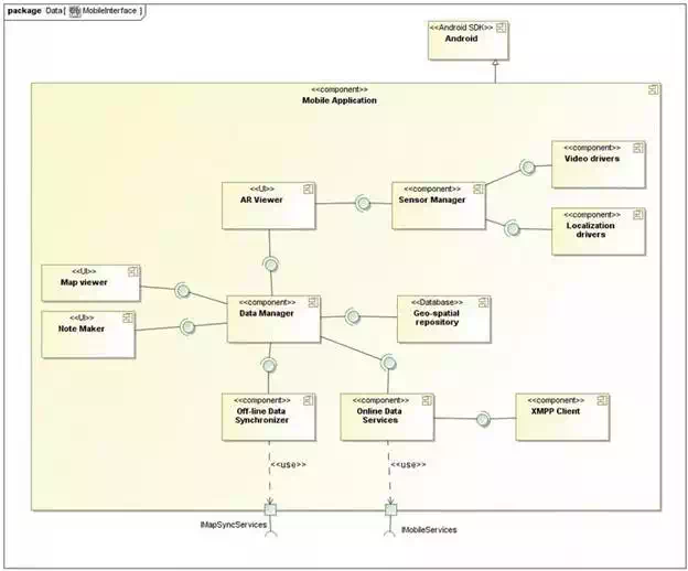
FIGURE 25.
Component architecture for the mobile application (source: ICARUS).
Offline data synchronizer: This component allows the mobile devices to upload the system with the data gathered from the mobile devices on the field and vice versa; it allows updating the mobile devices with the information storage in the main system. The synchronization of the data has to be guaranteed without any type of net communication.
Online data services: This component is responsible for data sharing between the mobile application and the RC2. Two separate implementations are foreseen within this component, one focusing on text/voice message exchange and the other focusing on location data exchange. The component is primarily responsible for handling connections and data flow using the native android socket API. For the location data exchange, it will expose a socket for the data manager to share device location data and receive location data from other devices (mobile devices and the RC2). For text messaging, it will expose a socket for the XMPP client to send and receive text messages.
Data manager: The data manager is responsible for handling and distributing geospatial information. It services requests for geospatial data primarily from the map viewer and note components. As all data within the mobile application can be considered geospatial (including notes taken at a particular location), the data manager provides get/set methods for each of these UI components. It handles database read and write functionality and ensures that all geo-data is maintained in a consistent manner. In addition, the data manager maintains all communications with external data services.
Geospatial repository: This component allows to store geospatial information in the mobile device, allowing it to work either offline and online.
Map viewer: This component allows the end-user to see the geospatial information available for the system in a map viewer. In addition, this component provides the basic functionality (zoom in, zoom put, pan) for the navigation through the map.
Note maker: This component allows the end-user to introduce a note marker within the map. The end user can tap/click over the map at any location and this component provides a menu to setup note and its message.
Chat client: The mobile application will provide the user with an UI to create, send, receive and track text messages with the RC2 and other mobile devices. It uses the Extensible Messaging and Presence Protocol (XMPP) to provide instant messaging (text and voice messaging) functionality. The XMPP client interacts with an XMPP server that runs on the RC2.
Map client viewer: The aim of the map client viewer is to provide a view of the mobile application user’s surroundings overlaid with relevant geospatial and mission-specific data as map layers.
Sensor manager: The sensor manager provides the map client viewer with access to the device sensor hardware, that is, cameras, GPS, gyroscopes and accelerometers. The sensor manager will provide methods to access the data from these devices using the Android SDK. Device’s location data, provided by the GPS or GSM localization and images or videos captured by the mobile device, are geo-tagged and shared between the other C2I subsystems.
Figure 26 depicts the global software architecture of the exoskeleton component. This component is composed of the exoskeleton device associated with the haptic controller (HACO) running on a dedicated computer.
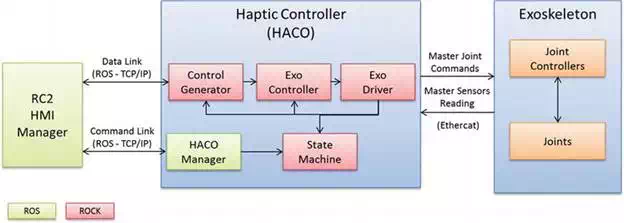
FIGURE 26.
Global software architecture of the exoskeleton device (source: ICARUS).
HACO is implemented on a Linux platform, running ROS and ROCK frameworks. ROCK is a software framework for the development of robotic systems. Running on top of the Orocos Real-Time Toolkit (RTT), it provides the tools to setup and run high-performance, real-time and reliable robotic systems. It is used here to implement internal function of the exoskeleton or running in the haptic loop that requires real-time, deterministic and fast operations (red blocks). The haptic loop is typically running at 1 kHz. The other modules for configurations, communications with the RC2 and management of HACO that do not require high update rate are running in ROS (green blocks). The exchange of data between ROS and ROCK is performed through the ROCK/ROS bridge interface provided by the ROS framework. The following modules in Figure 27 are implemented in HACO:
● HACO manager [ROS]:
○ Responsible for the configuration, management and monitoring of HACO
○ Interfaces the RC2 HMI manager through the command link that is a ‘low-rate’ communication link for remote status monitoring, commands and control parameters settings
● State machine [ROCK]:
○ Implements a state machine engine that allows defining HACO modules behaviour based on internal and external events. Internal events are events related to the operations of the exoskeleton (error in low-level joint controller’s communication, exoskeleton switch triggering, etc.). External events are messages received from the command link (start/stop, control modes, etc.) and transmitted by the HACO manager.
● Control generator [ROCK]:
○ Interfaces the RC2 through the data link that is a ‘high’ rate communication link with the slave device (e.g. UGV arm) for haptic control exchanges. This link is used in both directions to receive position and forces from the slave side and also to send master (exoskeleton) position and force data to command the slave device.
○ Computes position or force feedback set points (Cartesian space) for the exoskeleton controller based on the inputs received from the slave and the current status of the exoskeleton.
○ Implements Cartesian Space features like guiding forces or Cartesian workspace limits.
● Exo Controller [ROCK]:
○ Computes the joint actuator commands according to the selected mode. This module is based on the knowledge of the exoskeleton kinematics and dynamics and is thus dedicated to this interface.
○ Converts the Cartesian set points provided by the control generator into joint set points for the exoskeleton (e.g. inverse kinematics, Jacobian transpose).
○ Implements the low-level haptic control schemes based on the comparison with the current exoskeleton sensor reading.
○ Implements joint space features like gravity compensation and software joint limits.
● Exo Driver [ROCK]:
○ Low-level interface with the joint controller boards embedded in the exoskeleton. The communication is based on EtherCAT that is well fitted for high-rate real-time and deterministic communication.
○ Sends master joint commands, reads exoskeleton sensors (position, torques and buttons) and publishes them for the other parts of the system (internal or external).
○ Implements the triggering system of the main haptic loop that is responsible to start at a constant rate (e.g. 1 kHz) one haptic loop step. The other blocks are driven by the output of the Exo Driver module.
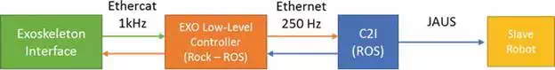
FIGURE 27.
Exoskeleton control architecture (source: ICARUS).
Each joint of the exoskeleton is equipped with a joint controller that:
● Acquires torque and encoder signals
● Implements low-level control of the joint and PWM drive based on the received master joint commands (e.g. position or current set point)
● Interfaces the Exo Driver through EtherCAT communication bus
PORTABLE HARDWARE RC2 PLATFORM
Designed to operate in rough environment, the RC2 box has the full capability of controlling the UAVs, UGVs and USVs in both tele-operated and autonomous modes. It is equipped with a semi-rugged Dell E6430 ATG laptop docked on a rugged docking station, which is the interface between the robots and the user (Figure 28). Many options are available to control the drones: two embedded joysticks, a wireless game controller and a mouse. The user will also be able to monitor the different parameters of the mission thanks to an additional 15.6″ screen. Two powerful batteries give an operating time of 8 hours and power the different parts of the box: the laptop, the optional light, the fan, the screen and the powerful telescopic antenna. In order to communicate with the RC2, some external USB ports and Ethernet connector are also available. Easy to set up, the user will quickly be able to have the RC2 operational.
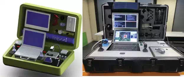
FIGURE 28.
Portable RC2 CAD model (left) and finished RC2 rugged system (right) (source: ICARUS).
EXOSKELETON HARDWARE DESIGN AND PROTOTYPE
The force-feedback exoskeleton interface is composed of two main components, the 7 DOF arm (from the shoulder to the wrist) and the hand exoskeleton. Several modifications have been brought to the arm exoskeleton, compared to the first version built in the past for ESA under the EXOSTATION project. The main modification is the material and manufacturing process used for the building of the structure. The new version is mainly based on rapid prototyping process (laser sintering) with alumide (composite aluminium and polyamide) and PA-GF (glass fibre-reinforced polyamide). Despite less rigidity of the manufacturing material, this allows a larger panel of shapes, as well as the integration of features (passing cable, fixation holes, etc.). Finite Element Analysis (FEM) analysis allows us to design a structure with comparable mechanical behaviour than the first version, with a slight reduction of weight. The kinematic configuration of the shoulder has also been updated in order to increase the achievable workspace within the exoskeleton, mainly when the arm is in the vicinity of the body. A half-circle curved guiding rail replaces now the full circle bearing on the upper arm. That improves the mechanical interaction with the body as well as facilitates the installation inside the exoskeleton.
The large unmanned ground vehicle is equipped with a 5DOF manipulator arm (Figure 29). The manipulator is hydraulic powered and consists of three rotational joints and two hydraulic cylinders. All five joints are feedback controlled by two external FPGA-based low-level controllers. These allow the actuation of the manipulator from remote and in an automated way. For each of the feedback controlled actuators, it is possible to set a desired position and a desired velocity and to receive the actual sensor values for the actuator positions and velocities. Additionally, the actual pressure values in the hydraulic joints are provided. The controllers are interfaced by the computer which runs the main control software of the Large Unmanned Ground Vehicle (LUGV). There the joint positions and velocities are transformed to a more convenient and sophisticated interface. All joint actuator sensor and control values are converted to joint angles and angular velocities which meet the Denavit-Hartenberg convention. The high-level control software is also responsible for safe operation and initialization of the two low-level controllers. Therefore, the operational state of both controllers is observed and synchronized, and the validity of the inputs is checked. This avoids unexpected behaviour during the initialization and operation phase, e.g. sudden movements or malfunction of single manipulator joints.
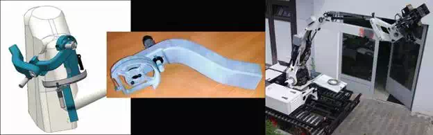
FIGURE 29.
(i) SAM exoskeleton upper part advanced design and rapid prototyping part integration test. (ii) LUGV with extended manipulator (source: ICARUS).
C2I subsystem integration and field deployment
MAP INTERFACE
The central widget in Figures 30 and 31 of the RC2 is the map interface.
● Multiple layers are provided as base maps, mission planning and robot positons.
● A zoom and pan option is provided for the user to navigate through the map layers using a standard mouse interface.
● The base maps consist of layers for
○ Military maps (e.g., test site Marche-en-Famenne)
○ Satellite, elevation and vectorial (roads, buildings, etc.) maps for the Moia CTC test area, Spain
○ Satellite and vectorial (roads, buildings, etc.) maps for the Portugal CINAV naval base
● Operational and mission planning layers consist of:
○ Robot layer
○ Waypoint layer
○ Sector layer
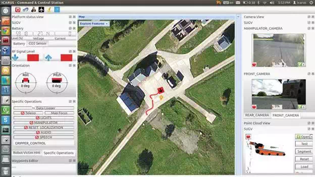
FIGURE 30.
C2I interface with maps, sensor visualizations and robot control (SUGV) (source: ICARUS).
MISSION PLANNING AND OPERATION
At the MPCS, the mission authoring tool illustrated in Figure 32 consists of the following:
● Adding virtual robots to the map at desired locations and constraining their activity within sectors.
● A sector can be freely drawn on the map using the ‘map context menu->draw sector’ tool. The sector drawing tool uses consecutive clicks on the map from the user to draw the polygon. The sector polygon can be modified by selecting the sector and option to drag and resize the sector and also deleted.
● A robot within the sector is then selected by the user and the associated context menu on the map allows the user to annotate the map with a set of waypoints associated with the robot.
● Each waypoint has an associated entry in the waypoint editor where the user can set specific parameters such as waypoint type (start, loiter, stop), velocity, altitude, waypoint tolerance, path tolerance, etc.
● On selecting the robot, a popup menu is displayed indicating user-driven interactions with the robot such as sending waypoints to the planner or the robot, hiding or showing waypoints on the map, constraining the robot to its bounding sector, etc.
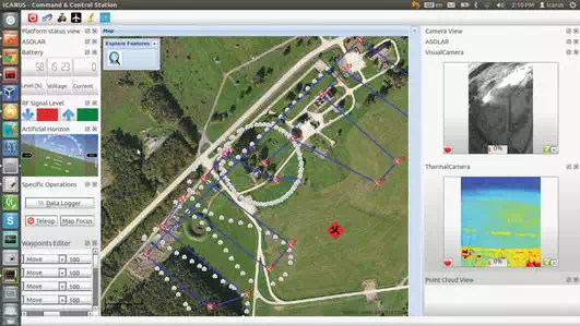
FIGURE 31.
C2I Mission plan execution with AtlantikSolar UAV (source: ICARUS).
AUTOMATED MISSION PLANNER
For the automated mission planner at the MPCS, the following requests are served (Figure 33):
● Path planning: The algorithm used is CUDA-based implementation of wavefront. The algorithm works with a 2D occupation grid map with user-defined waypoints as inputs (Figure 33), generated based on the semantic representation of the environment.
● Global path planning: The planners are able to give an answer to the travelling salesman problem. The implementation is based on a hill climbing algorithm, which allows for finding locally optimal solutions like scanning a sector as seen in Figure 33.
● Find optimal observation point: The planners are able to answer the question of optimal observation point of requested object with a given set of sensor. The representation of the environment is generated from the semantic model (Figure 34).
● Find optimal repeater position: Functionality for finding a spot from which the UGV could be working as a repeater. The query takes two disconnected signal sources that are weak to connect directly and simulates the disruption of the signal in the environment (Figure 35).
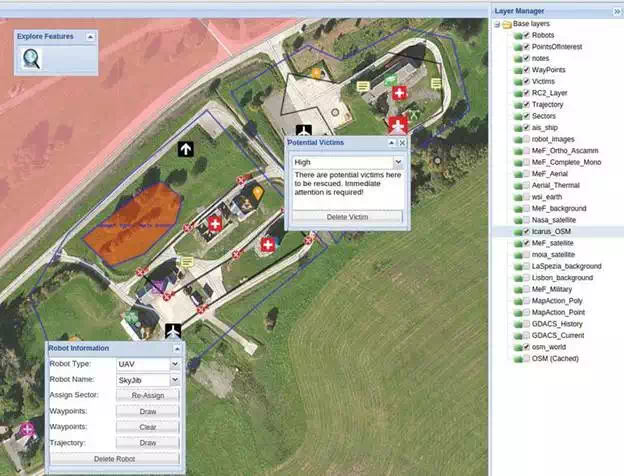
FIGURE 32.
Mission planning interface in the MPCS (source: ICARUS).
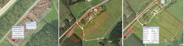
FIGURE 33.
(i) Automated mission planning queries. (ii) Sector scan query. (iii) Optimization of waypoint query (source: ICARUS).
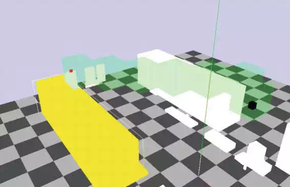
FIGURE 34.
Object observation point query visualization: black box, robot pose; red box, new robot pose (source: ICARUS).
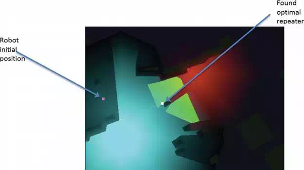
FIGURE 35.
Robot as repeater query: red, range of the first communication source; blue, range of the second communication source; green, potential positions that allow work as repeater (source: ICARUS).
The mission planners are using supporting tools. The most important one is the semantic environment model generation tools. The tools take 3D point clouds of a given area and generate a semantic representation of given area based on them. A simple model may be also generated based on GIS information. The semantic map divides the points into three main categories: ground, structured and unstructured (Figure 36). This allows for segmentation of single objects and making decision about traversability of a given terrain. Figure 37 shows the traversability analysis. Green points are traversable while red are not. Three examples in the picture were generated using different robot models. The semantic model may be used to generate virtual model of the terrain.
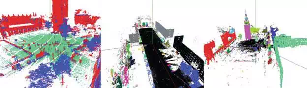
FIGURE 36.
(i) Point cloud classification of data from geodetic scanner. (ii and iii) Scene segmentation examples (source: ICARUS).
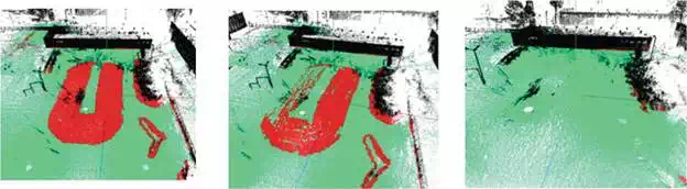
FIGURE 37.
The traversability analysis: traversability for UGV with 10° max slope, 18° max slope and 44° max slope (source: ICARUS).
RC2 VISUALIZATION AND CONTROL
Sensor visualizations in Figure 38 include the following dockable widgets:
● Robot pose:
○ The global NSEW orientation of the robot is shown on the map with the robot icon indicating the heading with an arrow.
○ The UAVs are provided with an artificial horizon that shows the roll and pitch, altitude and the rate of climb.
○ UGVs have two independent indicators for the roll and pitch of the robot.
● Camera viewer:
○ This component renders all the cameras that are streaming videos from a robot.
○ It contains dockable windows that can be resized, tabbed or undocked from the parent window to be positioned anywhere by the user. The rendered video resizes to the window while maintaining its aspect ratio.
● Waypoint editor:
○ Each waypoint associated with a robot is displayed in a list form.
○ Every parameter of the waypoint can be edited from this editor such as waypoint type (start, loiter, stop), velocity, altitude, waypoint tolerance, path tolerance, etc.
● Joystick selector:
○ This is a single button to switch the control of a robot to tele-op mode to select the appropriate joystick control.
● Point cloud renderer:
○ This widget can render raw point clouds from Lidar sensors or the global 3D map of the scanned that are provided by the robot.
● Battery and wireless status:
○ These are two independent-level indicators showing the current energy levels of a robot and the quality of the wireless network link (in percentage).
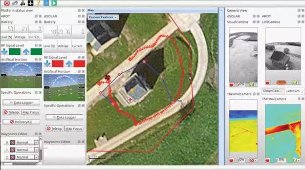
FIGURE 38.
C2I with AtlantikSolar UAV and AROT quadrotor (source: ICARUS).
A PS3 game pad connected to the RC2 via Bluetooth has been configured and interfaced with the C2I to tele-operate a robot. There are currently four axes of control and multiple buttons which can be used according to the type of platform. The joystick was used to control the UGVs and the quadrotors. Tele-operation of virtual robots in simulators has also been implemented and tested.
RC2-INTEGRATED TRAINING WITH SIMULATORS
The RC2 has been integrated with two simulators as per the reference network architecture in Figure 39for training purposes over ROS:
● The USAR training simulator (Figure 40) is capable of streaming virtual data such as videos from multiple virtual cameras, virtual global positon and orientation of the robot. This data can be rendered in the C2I similar to that of a real robot. Tele-operation of the virtual robot is also possible using the PS3 joystick controller. Remote streaming and control of the robot were achieved over the Internet with the C2I operating in Brussels and the UGV simulator hosted on a server in Poland within a VPN with standard (expected) delays over the Internet.
● The MSAR simulator (Figure 41) provides virtual data such as videos from multiple virtual cameras, virtual global positon and orientation of the robot, battery level and wireless link quality. These sensor data can be visualized in the C2I similar to a real USV.
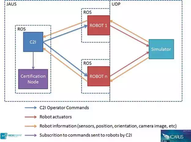
FIGURE 39.
Maritime simulator network architecture (source: ICARUS).
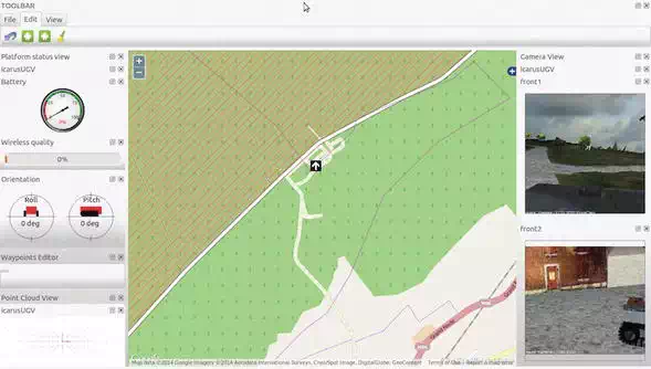
FIGURE 40.
RC2 with feed from ground robots in simulated environment (source: ICARUS).
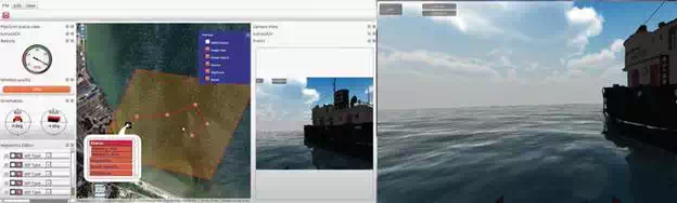
FIGURE 41.
Integration result (left, C2I; middle, robot controller; right, maritime simulator) (source: ICARUS).
Since the simulator will only simulate the sensorial/physical aspects of the robots, the connection between the C2I and the simulation is transparent and does not require any extra overhead in integration. The figure below shows the final integration between the simulator and the C2I.
C2I-JAUS CAPABILITIES
The ICARUS interoperability standard JAUS has been integrated with the C2I. The ‘JAUS-fleet’ is responsible for the automatic discovery of a robot within the JAUS network environment. The ‘JAUS-fleet’ sends a ROS-robot profile message indicating the addition of a new robot to the network. The C2I responds to this dynamic discovery by configuring the front-end user interface and visualizations corresponding to the type of robot (UAV, UGV or USV). Sensor data from the robot and commands from the C2I to the robot are sent via ROS topics which are also dynamically generated. The current level of compatibility of the C2I through the JAUS interface is as follows:
● Multiple-camera video streaming
● Four axis Joystick commands
● Sending waypoints with metadata (path and waypoint tolerance) to the robot
● Global pose of the robot (GPS and inertial data)
● Dynamic robot platform discovery
● Multi-robot operation capability
GIS DATASETS
The following environmental data have been integrated into ICARUS system:
● Moia-BBOX (41.818728 2.1773529, 41.803886 2.1482563) (Figure 42):
○ Vectorial data obtained from open street maps (OSM). Deployed in GeoServer and MapServer
○ Orthoimages for the Moia region and surroundings, obtained from the Spanish Geographical Institute (IGN). Deployed in MapServer
○ Vectorial data depicting slope, altitude, hydrography and roads. Deployed in MapServer and GeoServer
○ Vectorial data for Catalonia villages, boundaries, regions, municipalities and provinces. Deployed in MapServer and GeoServer
● Marche-en-Famenne-BBOX (50.264326 5.3996086, 50.254010 5.3782368) (Figure 43):
○ Vectorial data obtained from open street maps (OSM). Deployed in MapServer and GeoServer
○ Pyramidal raster data for the Marche-en-Famenne region, obtained from the Royal Military Academy (RMA). Deployed in GeoServer
○ Top-view raster from the test area, obtained from the Royal Military Academy (RMA). Deployed in GeoServer
● Lisbon-BBOX (38.667258 -9.100424, 38.649694 -9.1492938) (Figure 44):
○ Vectorial data obtained from open street maps (OSM). Deployed in GeoServer and MapServer
○ Raster satellite maps from openly available sources such as NASA earth, local government agencies, ESA Copernicus satellite imagery etc.
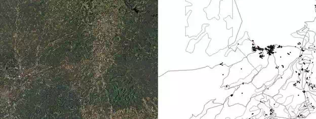
FIGURE 42.
Moia map data (source: ICARUS).
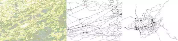
FIGURE 43.
Marche-en-Famenne map data (source: ICARUS).
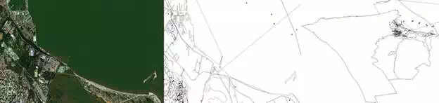
FIGURE 44.
Lisbon map data (source: ICARUS).
Apart from environment GIS information, ICARUS database schema defines some geospatial entities that have been defined and published as layers (zones, sectors, victim status, trajectories, structures, robots, missions, mission features, GDACS items, floor plans and waypoints)—GeoServer, MapServer.
GDACS provides a RSS with worldwide disaster event information. This data source has current disaster information and related information such as images, documents, URLs, etc. We have developed an application that dumps information to a spatial/GIS database. The data have the geographic positions that allow us to depict them on a map and consult related information. In order to safeguard the records related to each item of disaster, file types that are of interest are also copied. Item information retrieval in a Popup with right button click shows historic disasters evolution (Figure 45).
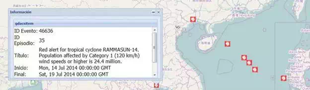
FIGURE 45.
Inspection of GDACS information in the C2I map application (source: ICARUS).
DATA FUSION MODULE
This module is currently divided into two big objectives: map generation and map segmentation. Figures 46 and 47 show the result of both entities, respectively.
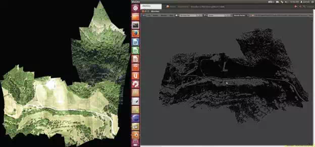
FIGURE 46.
Fast mapping results in 2D (textured, left) and 3D (sparse cloud, right) for flights in Moià (source: ICARUS).
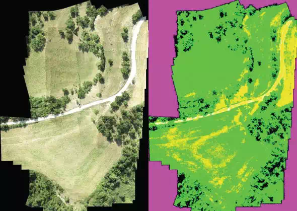
FIGURE 47.
(Left) Original map used to be classified, the same as shown in ground truth selection and preview of results over a map generated during the trials. (Right) Segmented map, prediction done by the service implemented in ROS (source: ICARUS).
MOBILE APPLICATION FOR FIRST RESPONDERS
The mobile application user interface (Figure 48) has been deployed on Android platform running version 4.2.2 or later. The application will provide the following features:
● Maps: The application connects to the MPCS and RC2 map server interfaces using HTTP and downloads map layers and associated content from the GIS. The map view will in addition to the maps overlay information such as current position of the user, team and robot positions.
● Text and image notes: The application provides a note-taking tool for the user to create text, image and video notes and tag them to his current position on the map.
● Other map features include the position of victims, points of interest, sector of operations, multiple base map layers (OSM, satellite, military maps, etc.) and a simple instant messaging platform for text communication between RC2 operators and other mobile devices.
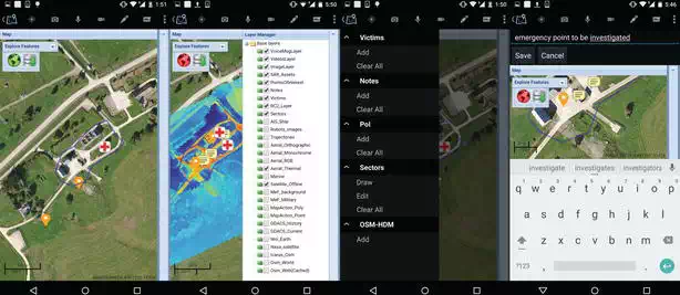
FIGURE 48.
User interface of the mobile application (source: ICARUS).
EXOSKELETON INTERFACE WITH UGV MANIPULATOR
The exoskeleton was employed with the C2I to provide an intuitive manipulation interface for manipulators of the sensor visualizations and robot control (SUGV) and the LUGV. During operation, the operator was wearing the exoskeleton device beside the C2I system in order to be able to see the on-board slave robot’s cameras (e.g. zoom on the gripper) and the slave robot arm model simulations (view of robot state based on collected data), helping him for precise manipulation and operations. Thanks to the triggering system, it was easy to enable and disable the control link with the slave arm. Figure 46illustrates the operation of the SUGV with the exoskeleton during the final demo. The exoskeleton was used to control with dexterity the slave arm with the objective to open a door handle. Compared to a standard joystick or pad controller, this solution allowed being more accurate and quicker, with the capacity to transfer to the robot the good motion for the handle operation. Figures 49 and 50 highlight the operation of the LUGV with the exoskeleton that was performed during the preparation phases.
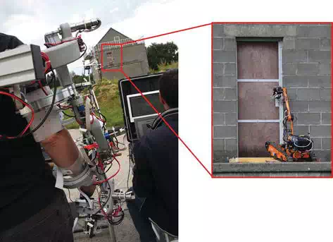
FIGURE 49.
Control of the SUGV with the exoskeleton interface in operational scenario to operate a door handle (source: ICARUS).
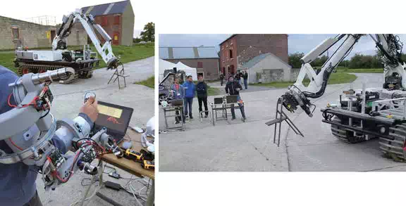
FIGURE 50.
Control of the LUGV with the exoskeleton interface to grab objects (source: ICARUS).
Conclusions
The C2I system of the ICARUS project is an essential set of hardware and software components, instrumental in providing interfaces for SAR responders to get a common operation picture for supervising SAR tasks. The MPCS, RC2, exoskeleton and mobile field devices of the C2I system provide a distributed capability for planning and controlling unmanned robots and SAR personnel, thus improving the effectiveness of the response to crisis situations. Offline mission planning capability coupled with human in the loop commanding a fleet of tele-operated and semi-autonomous robots during SAR operations demonstrated the effectiveness of such a system. Future enhancements to the C2I include runtime operational mission planning and immersive 3D HMI interfaced with advancements in robot autonomy and fault-tolerant multi-robot cooperation. Field demonstrations of the C2I system with SAR personnel assisted by unmanned systems provide an outlook for implementing such systems into mainstream SAR operations in the future. The flexibility of integrating the C2I with diverse robotic platforms will enable a large variety of robots to be tested, evaluated and eventually used in SAR operations.