Tactical Communications for Cooperative SAR Robot Missions
First responders’ communications (COM) have become a key concern in large crisis events which involve numerous organisations, human responders and an increasing amount of unmanned systems which offer precious but bandwidth‐hungry situational awareness capabilities.
The ICARUS team in charge of developing the COM system — lead by INTEGRASYS with contributions from RMA and QUOBIS — has designed, implemented and tested in real‐life conditions an integrated multi‐radio tactical network able to fulfil the new demands of cooperating high‐tech search and rescue teams acting in incident spots. The ICARUS network offers interoperable and reliable communications with particular consideration of cooperative unmanned air, sea and land vehicles.
In this chapter, we provide a description of the different phases. Starting with requirements collected from high‐level mission managers and specific platform operators, we describe the key design decisions taken by the COM team to follow with implementation details and finalising with the COM system results obtained during the different trials conducted by the project.
Communication scenarios and requirements
Proper communication systems are needed to ensure the networking capability that allows SAR team members (robots and humans) and operations managers to share real‐time information under the hostile operating conditions characterising disaster‐relief operations. These conditions mandate the use of wireless communication technologies to support the inherent mobility nature of operations.
Figure 1 depicts the general information exchanges occurring in typical disaster‐relief operations where multiple SAR teams are actuating. An entity named on‐site operations coordination centre (OSOCC) acts as the central coordination centre for all operations and is placed close to the disaster zone. First, area reduction and sectorisation tasks are performed by the OSOC to quickly identify and analyse priority actuation areas so as to allocate specific sectors to available SAR teams. These initial planning activities are likely done by the OSOCC with the support of unmanned assets of SAR team temporarily collocated with the OSOCC.
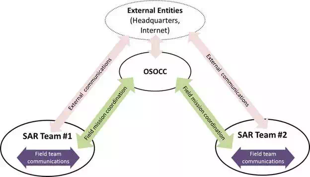
FIGURE 1.
High‐level communications in ICARUS. (Source: ICARUS).
The SAR teams are groups of first responders equipped with unmanned vehicles that perform SAR operations in an allocated area. They use team‐internal communications (labelled Field Team Communications in the figure) to perform their activities, in particular sharing sensor information captured by human or robotic responders and commanding unmanned vehicles from control stations. The SAR team activities are supervised and coordinated by the OSSOC using field mission communications, which serve, for example, to report about rescued victims, current team‐members’ location, new actuation areas, etc. Both the OSOCC and the SAR teams may make use of external communications with distant entities, such as agencies headquarters for logistic coordination, or data servers providing background or newly acquired information about the disaster area.
Building upon the reference ICARUS communication scenario described above, the ICARUS COM team worked in closed cooperation with other project teams to gather a list of relevant requirements to guide the COM system design and further implementation. Feedback obtained from end‐users (SAR organisations) participating in the project either as partners or as end user board (EUB) experts was used to compile a list of essential high‐level requirements, which is shown in Table 1. From this list, we highlight in particular the need of using non‐reserved spectrum for the operations, due to the likely impossibility of using pre‐existing local communication infrastructures and coordinating with the national spectrum regulation in the early phases of a crisis event.

Furthermore, in collaboration with the different project teams in charge of defining overall user requirements, providing unmanned platforms and developing the interoperable Command & Control (C2) tools, an extended view of the communication architecture was elaborated together with a list of quantitative performance target for the ICARUS COM system, based on expected equipment sizing of future SAR teams.
Figure 2 shows the refined view of the communications architecture where the field team communications within a SAR team operation area are populated with different entities and networking segments. This architecture constitutes the reference ICARUS communication model and reflects the typical command and control architecture of future SAR missions making use of ICARUS tools. Each SAR team has a base of operations (BoO) entity which coordinates different squads, namely a group of human and robot responders working in a specific spot within the assigned SAT team area. Making use of a Squad coordination network, each squad operates its unmanned assets through a robot command and control (RC2) station, which additionally serves as a base station for human communications, either voice‐based or message‐based. The BoO receives mission guidance and reports mission status to the OSOCC through the team coordination network segment and at the same time executes the assigned team mission in coordination with the different squads through the team coordination network segment. In Figure 2, it can be seen several COM management entities, residing on the different system entities forming a hierarchical structure that will cooperatively perform all management and control functions on underlying COM resources to allow first responders and their tools to be smoothly interconnected during operations. The network segmentation shown in Figure 2 does not assume a corresponding physical segmentation in terms of frequency channels, link‐level networks or IP‐level networks; it is rather a logical organisation resembling the working structure of teams.
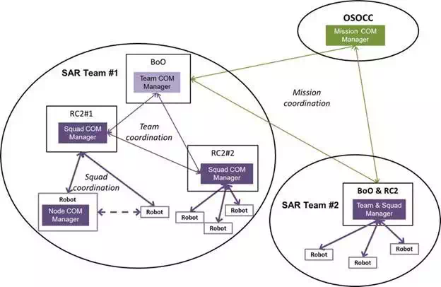
FIGURE 2.
High‐level communication segments in ICARUS. (Source: ICARUS).
Table 2 gathers the list of key performance targets for the ICARUS COM system elaborated in cooperation with end user organisations, unmanned platform providers and C2 system providers. The reference team networking scenario consists of several interconnected squads operating in cell areas with a maximum radius of 1500 m and five nodes, including a R2C station, which should be able to transition across squads within a limited time. A mix of synchronous/asynchronous application traffic is transferred within squads, between the squads and with the OSOCC. The estimated peak capacities include typical video, voice and Telemetry/Telecommand (TM/TC) feeds.

Pre‐existing solutions and design decisions
Providing reliable wireless connectivity during disaster relief presents a significant challenge. For robust and effective disaster response, mesh wireless networking technology presents a solution to create adaptive network in emergency scenarios in which support infrastructure is either scare or non‐existent. A flexible mesh network architecture that provides a common networking platform for heterogeneous multi‐operator networks, for operation in case of emergencies, is proposed in Ref. In Ref., the authors have proposed an approach to establish a wireless access network on‐the‐fly in a disaster‐hit area relying on the surviving access points or base stations, and end‐user mobile devices. Similar works also appear in Refs. An ad hoc networking solution is proposed in Ref. to aid emergency response relying on WiFi‐Direct enabled consumer electronic devices such as smartphones, tablets, and laptops. An integrated communication system is proposed in Ref. comprising heterogeneous wireless networks to facilitate communication and information collection on the disaster site. Based on WiMAX technology, without fixed access point, an ad hoc networking solution is proposed in Ref. using UAV relays to realise a backbone network during emergency situations. Similar concept is proposed in Ref. using IEEE802.11s. Arecent work in Ref. employs dual wireless access technology for robotic assisted SAR operations–one technology to provide a long‐range, single‐hop, low bandwidth network for coordination and control of the robotic devices and second technology for short‐range, multi‐hop, high‐bandwidth network for sensor data collection. Ref. proposes a framework for modelling and simulating the communication networks and examining the ways in which availability, quality of the communication links, and the user engagement affect the overall delays in disaster management and relief. Leveraging the latest advances in wireless networking and unmanned robotic devices, Ref. proposes a framework and network architecture for effective disaster prediction, assessment and relief.
As we have seen in the previous sections, the ICARUS SAR scenario demands QoS‐enforced wireless communications for different types of nodes (robots and stations) spread over a relatively large area in order to provide proper throughput, latency and reliability for the different applications needed to support the missions. Furthermore, future robotic C2 systems enabling higher autonomy – for example, those supported by the JAUS framework selected in ICARUS − will dynamically use centralised and decentralised algorithms, demanding from the communications layer the ability to have a flexible balance of the uplink (transmission) and downlink (reception) capacity of network nodes.
Previous research or demonstration activities dealing with a cooperative robotic scenario similar to ICARUS have commonly deployed different technologies, either standards‐based such as PMR (Professional Mobile Radio, e.g. TETRA), WLAN (802.11 family of standards), WPAN (802.15.4 family) and WMAN (802.16 family), or proprietary‐based solutions in licensed or unlicensed spectrum; complemented with public services such as 3G/4G or WiMax, in case these were available at the operations area. As no single communication technology is able to satisfy the varied set of requirements usually demanded by the users, a combination of several datalinks is recurrently used to provide the communication service.
In order to facilitate the selection of the most appropriate datalink technologies for ICARUS, a reduced set of operational and technology challenges to be solved in order to provide a proper, real‐world communication solution for the posed scenario was defined in cooperation with end users. These challenges are shown on the left side of Table 3, followed at the right side by the corresponding approaches taken by the COM team to address them building upon existing datalinks.
TABLE 3.
Key communication challenges in robotic SAR scenarios and the ICARUS responses.
While the various datalink technologies surveyed present rather different features and capabilities, the COM team focused on the specific set of wanted characteristics that served most to solve the challenges identified. As an example, in the following, we list some of the key wanted features at the datalink level.
● Dynamic channel selection and frequency hopping to improve reliability in unlicensed spectrum where multiple competing networks may exist.
● Multi‐hop capable datalinks or the lowest possible spectrum bands (e.g. 433 and 868 MHz) looking for favourable propagation conditions to achieve long ranges in unlicensed spectrum. Both approaches come at the expense of reduced bandwidth.
● Modulations resilient to non‐line‐of‐sight conditions, link diversity solutions (e.g. link meshing or MIMO antennas), and rate and transmission power control to cope with variable link conditions experienced by mobile nodes, subject, for example, to blocking obstacles.
● Proper QoS techniques to avoid network congestion while guaranteeing performance for the individual flows generated at the different nodes. QoS can be guaranteed on a deterministic basis with a channel access scheme based (at least partially) on time‐slots allocation, which requires time synchronisation between network nodes and may add significant control traffic overhead if frequent reallocation of capacities is needed. QoS performance highly depends on network topology, and some datalink technologies (e.g. those used in sensor networks) are designed for specific application cases (e.g. cluster‐tree topologies), which limits usability in the ICARUS scenarios.
These considerations on datalink technologies must be traded‐off with wanted high‐level system features and overall non‐functional requirements, as stated in Table 3, observing at all times the need to have an affordable solution.
From a system level perspective, ICARUS C2 applications are operating upon the JAUS middleware, assuming transparent IP connectivity between the different end nodes. Therefore, solutions are needed to integrate the different datalink technologies and link‐layer subnetworks in an interoperable IP addressing space and to properly propagate QoS settings for different exchanges from the middleware level down to the datalink layers. Some datalink technologies are not IP‐capable due to resource constrains of the node platforms (e.g. sensors), which adds further difficulty leading to the implementation of IP gateways which must properly translate all needed IP protocols to the link layer. On the other hand, a specific requirement is the ability to transfer the control of robots between different stations operation potentially in different areas, so roaming over different network segments would be required. There are generic solutions at the IP level which provide multi‐homing and mobility support but are rarely applied in ICARUS‐like scenarios due to the effort needed to synchronise mechanisms at IP‐level with those needed at the underlying link‐level for the several datalink technologies used.
Having all of the above considerations in mind a detailed comparative study of available solutions was made, resulting in the final selection of the following technologies:
● ETSI digital mobile radio (DMR) datalink for long‐range low‐rate communications between control stations and robots. Aiming at an open and affordable hardware implementation using commercial components, a Tier‐2 direct‐mode operation is selected with multiple coding options to avail of capacity versus range flexibility. This is extended with software‐based functions allowing valuable services such as node discovery and capacity management. The latter allows to accommodate different traffic arrival patters latency requirements procuring maximum network utilisation.
● IEEE 802.11n network with meshed multi‐hop support to interconnect the different squads, teams and the OSOCC. Building upon commercial transceivers, extended management and control functions based on open Linux‐based software are identified to achieve high performance in ICARUS environments, based on the smart handling of channel, power/rate, CSMA and EDCA parameters. Spectrum‐level functions such as channel selection and power control are supported by cognitive radio techniques, aiming at operation with minimum interference and maximum spatial reusability conditions. The use of such cognitive radio features in disaster response networks offers opportunities to adapt communication links to the various changes in the operating environment and thereby enhance the performance of the communication network.
The proper integration, extension and smart utilisation of the two types of datalink selected are expected to provide the concrete responses to the ICARUS COM challenges found at the right side of Table 3, which form the key design aspects of the ICARUS COM solution.
The implemented ICARUS COM system
INTEROPERABILITY, PERFORMANCE AND MANAGEABILITY FUNCTIONS
The ICARUS COM team approach to implement the required networking capability for SAR missions is to implement key software‐based functions upon well‐established, commercial datalink technologies offering managed performance levels with enough predictability. The combined set of functions will ensure instant interoperability among the variety of unmanned vehicles, personal devices and control stations and will enable performance optimisation by adapting to changing conditions due, for example, to nodes mobility, propagation environment, external interference or evolving mission needs.
The implemented ICARUS COM functions are grouped in three different areas: (a) radio resources management, (b) IP protocol addressing and routing management and (c) overall management and control (M&C).
At radio resources level, ICARUS implements a distributed cognitive radio capability to allow dynamic channel selection (frequency and width) over different unlicensed spectrum bands – 433 MHz, 870 MHz, 2.4 GHz and 5 GHz – for the whole set of datalinks and network segments used in the system. An innovative combination of raw spectrum monitoring with physical and link layer measurements from network devices provides a global view for channel selection as well as a per‐link view to quickly detect problems and take proper correction actions; procuring at the same time implementation of required regulation rules to access given spectrum bands.
At IP protocol layer, a single virtual IP network is offered to applications building upon native operating system tools. Rather than providing a single IP to each system platform (robot or control station), an IP subnet sized for six different addresses is allocated, so that different physical nodes corresponding the same platform (e.g. main computer and standalone cameras on‐board the same vehicle) can access to the ICARUS communication capability available on a dedicate COM computer hosting the COM software and datalinks. Proper routing functions ensure that unicast and multicast application traffic running over the virtual IP network smoothly traverses multiple wired and wireless link‐layer segments.
All of the IP traffic handled in the ICARUS is QoS marked so that proper processing can be done first within the IP stacks of the system nodes and further within the operating datalink layer. In SAR communications, it is imperative to be able to handle different application flows with different QoS giving priority to certain types of data. Based on the defined requirements in Section 2, a number of traffic classes have been defined in the ICARUS COM system, which are shown in Table 4 detailing the differentiating characteristics and typical application flows making use of them.
At overall M&C level, a coordinated set of managers and controllers’ modules is designed to handle the traffic generated from the JAUS application middleware to be properly transferred through the underlying datalinks. To that end, the COM layer implements automated JAUS traffic identification and subsequent QoS allocation based on a set of predefined and run‐time reconfigurable rules so that no change is needed on existing applications to benefit from the managed communication capacity of ICARUS so that custom application MW traffic processing in COM easy‐to‐use software interfacing mechanism will be provided within the middleware itself. In addition to passing data units, applications will use the interface to select applicable QoS parameters, while the COM layer will provide relevant information about connectivity (e.g. reachability of other nodes, capacity limits, etc.) using the same naming rules used by the middleware. In this way, control algorithms can conveniently include communication status information to take better decisions.
THE ARCHITECTURE OF THE ICARUS COM NODES
The set of COM functions briefly introduced in the previous section is implemented in the form of software modules residing in computing nodes associated with the different system entities, namely unmanned vehicles and corresponding control stations, personal devices and mission coordination stations. The various software modules need to efficiently interface with each other — either within the same or over different platforms nodes — to undertake different control, data or management functions. In order to facilitate the implementation of the ICARUS COM system as well to allow for future extensibility, well‐structured and formal mechanisms were defined to model, develop and deploy the different ICARUS software modules. The set of core modules supporting this mechanism and implementing essential system functions is known as the ICARUS COM middleware (COMMW). The COMMW enables the implementation of cooperative and specialised management and control functions and has therefore been a key piece enabling interoperable and resilient tactical communications in the ICARUS scenario of crisis response operations covering air/sea/land portable and mobile nodes.
Figure 3 represents the key COM modules residing in the four different nodes forming a single robot control setup. Two of them (APPNODEs) represent the main computers aboard a robot and at the RC2 station hosting all the software needed for controlling and supervising the platform and its payload sensors. The other two (COMNODEs) are small computers linked through Ethernet connection to their corresponding application nodes acting as data routers providing access to the ICARUS wireless network. In the case of the RC2 station, management and control interfaces are also established between given entities at communication and application levels for overall monitoring and control of mission communications during operations. In the figure, there can be easily identified the different layers constituting the ICARUS COMMW.
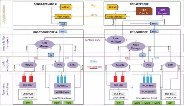
FIGURE 3.
High‐level communication segments in ICARUS. (Source: ICARUS).
The COMMW has been implemented on open, Linux‐based embedded computing platforms with proper kernel and user‐space extensions enabling an overall optimisation of the network stack, including the queuing components present in the system data path, which may largely affect throughput and latency of applications. Figure 4 below shows the final aspect of the assembled COM computer mounted aboard the so called LUGV (Large Unmanned Ground Vehicle) ICARUS robot.

FIGURE 4.
SUGV COM box and set of antennas used in various missions. (Source: ICARUS).
The COMMW framework seamlessly integrates and jointly manages both WLAN and DMR datalinks according to dynamic mission conditions and evolving requirements. In the following sections, we describe the key datalink‐specific functions implemented.
DMR DATALINK IMPLEMENTATION
The DMR datalink technology standardised by ETSI provides long range coverage (typically beyond 5 km in open areas) and can handle both voice and low‐rate data. The so‐called soft‐DMR modem implemented in ICARUS enables adaptation of key transmission parameters — coding rate, delivery mode, channel access mode and transmission power — on a per‐destination basis, according to QoS requirements (Table 4) of the currently handled application data. As ICARUS extensions to the DMR Tier‐2 technology, a node discovery service and a capacity management protocol (allowing allocation of throughput levels per node) were implemented to strength the networking aspects of DMR. All these characteristics make the soft‐DMR well suited for networked tactical and mission critical applications.
The following Figure 5 shows the final DMR modem board implemented together with an average ballpoint pen for size comparison purposes.

FIGURE 5.
ICARUS DMR hardware transceiver. (Source: ICARUS).
WLAN DATALINK IMPLEMENTATION
ICARUS WLAN datalinks are based on 802.11n commercial transceivers with 2 × 2 MIMO antenna configuration which was assessed as a fair setup to operate in the variety of radio propagation conditions existing in ICARUS missions. All used transceivers are equipped with an Atheros dual‐band chipset supported by the Ath9k Linux driver, which is the common basis to develop low‐level ICARUS extensions. Full‐mesh capability spanning multiple frequency channels is provided through the 802.11s Linux implementation, properly configured to allow a smooth behaviour of mesh peering and routing algorithms given the particular mobility and radio link conditions expected for ICARUS nodes.
Specific functions deployed in Kernel space for performance reasons allow the fine control of key system parameters affecting the overall network performance — particularly range and throughput — which are optimised in real‐time according to predefined and reconfigurable operator policies. These parameters refer to three distinct areas:
● At radio link level, the controlled parameters are: radio bands and channels frequencies and widths; transmitted power, rate control policy, frame retry policy and waveform mode (e.g. 11b, 11g, or 11n). Legacy waveforms are eventually used for nodes under particularly disadvantaged radio conditions, for example, located at long distances or in indoor.
● At channel access level, the controlled parameters are per‐class EDCA contention parameters and the CSMA carrier sense level.
● At mesh protocols levels, the controlled parameters are timers and counters associated with paths and peers’ discovery and association protocols; and to the configuration of root and gateway nodes.
OPERATIONAL MANAGEMENT
In parallel to the implementation of COM managers and controller modules, the ICARUS COM team worked in the development of a convenient set of tools to ease the tasks of operators responsible for communications during the different mission phases (planning, deployment, operation) aiming at simplified and fast manual interventions while having proper information and tools at all times to fine‐tune key parameters affecting the performance of the overall network and specific links.
There are two different toolsets offered to network operators. The first one is a configuration tool based on a structured data model which allows to setup the overall node configuration based on capacity allocation targets for both locally‐generated and relayed traffic; differentiating among individual application flows and supporting latency, reliability and security requirements in addition to throughput. Operators are provided with a set of utilities for guidance on setting the different configuration parameters. Some of the settings will be subject to dynamic changes during mission execution.
The second one is a rich graphical environment named COM console (COMCON) conceived to support planning, supervision and optimisation of the integrated multi‐radio ICARUS network, combining simulation features with real‐time monitoring and control capabilities. In both simulation and real‐time modes, the COMCON tool acts as a visualisation and control frontend for the COMMW modules. The COMCON tool is able to represent with high‐fidelity the time behaviour of the ICARUS network with fine‐grained view and control of a number of interrelated physical or system factors, which influence the performance of specific links and the overall network.
At planning phase, the COMCON tool accurately characterises COM components, propagation environments, RF interference and vehicles platforms in order to assess global network performance over wide operation areas; as well as the performance of individual terminals along given mission routes. This allows in particular to take proper decisions on radio bands and channels, antennas pattern/polarisation and transceiver features for every node in the network. Furthermore, the eventual need and location of network relays can be assessed. The tool includes propagation models for indoor, rubble and sea environments in UHF/2.4 GHz/5 GHz bands; as well as protocol models of 802.11 mesh networks enabling informed planning of CSMA‐related parameters and reliable estimation of throughput performance. Figure 6 exemplifies a mission modelled in the COMCON tool where the different links and antenna coverages of networking nodes are calculated and verified during mission planning in an interactive 3D Earth Globe visualisation interface.

FIGURE 6.
ICARUS COM console used in mission planning. (Source: ICARUS).
At operations phase, the COMCON features a centralised monitoring of all key parameters affecting the network performance, allowing to mitigate coverage and throughput problems by timely reconfiguration and eventual reallocation of nodes. Figure 7 shows an example of a real mission monitoring display offering connectivity as well as link performance information to the operator.

FIGURE 7.
ICARUS COM console in mission operations. (Source: ICARUS).
Some optimisation actions of limited impact are performed automatically by the COMMW stacks, while some others of wider scope require human operator intervention to decide the best solution given the current mission conditions. Of special relevance to network operators is the ability of the combined COMMW software and COMCON tool to determine the likely reason of detected traffic losses, leading to different corrections. The traffic losses are classified in four different groups:
● Collisions, which can be solved by forcing RTS/CTS, changing paths or moving nodes
● External interference, which can be solved by selecting new channels or changing the channel bandwidth
● Propagation conditions, which can be solved relocating nodes, moving to basic transmission modes
● Queuing, reflecting packet drops in different system queues, which can be solved limiting application demand
Field validation and conclusions
During the final project demonstrations conducted at the Almada Camp of the Portuguese Navy and the Roi Albert Camp of the Belgium Army, the ICARUS COM system and associated tools have proven to offer significant value for mission commanders along different mission phases, as illustrated on Figures 8–10. First, as a powerful deployment planning tool and second, as a network management and optimisation tool able to seamlessly connect all robots’ telemetry and tele‐control capabilities to the ICARUS C2I stations, mitigating eventual coverage and throughput shortcomings arising during operations.
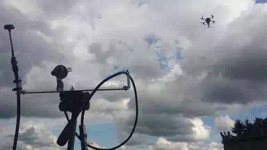
FIGURE 8.
ICARUS COM tools communicating with aerial robotic systems (acting as communication relays). (Source: ICARUS).

FIGURE 9.
ICARUS COM tools communicating to rescue workers operating inside a rubble field. (Source: ICARUS).
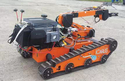
FIGURE 10.
ICARUS COM tools installed on a small unmanned ground vehicle. (Source: ICARUS).
The ICARUS communication system makes use of HW/SW mass‐market technologies thoroughly engineered for professional performance exploiting unlicensed spectrum in UHF, 2.4 and 5 GHz bands. The “unlicensed spectrum” approach has provided acceptable performance during the set of trials executed during the project life under limited interference conditions. Nevertheless, in real‐life safety‐critical SAR operations, it is highly desirable having guaranteed access to radio spectrum with proper EIRP limits to ensure required throughput and operation in long ranges or harsh propagation scenarios such as rubble or indoor. The ICARUS communication system includes by‐design specific provisions to ease integration of new datalink technologies and extend operation to new frequency bands, by adapting the cognitive radio functions to implement any required spectrum access rules. Existing 802.11 COTS professional transceivers that can be tuned to operate in any band up to 6 GHz will allow to readily reuse all of the COMMW/COMCON 802.11 capabilities in low‐frequency spectrum particularly suitable and eventually protected for public protection and disaster relief (PPDR) applications. In the migration phase towards commercialisation, the team is also working on the integration of LTE services; either commercial (if available on crisis location) or PPDR‐specific (e.g. operating in the 700 MHz) to be used as a complementary incident‐spot capacity as an interconnection means between distant incident‐spots. While low‐layer LTE functions would be out of control of ICARUS COM reducing optimisation possibilities, the framework is already able to evaluate in real time the throughput and latency offered by external networks, which would be used to manage the available capacity as a whole.
The research leading to these results has received funding from the European Community’s Seventh Framework Programme (FP7/2007–2013) under grant agreement number 285417.

