Unmanned Maritime Systems for Search and Rescue
During maritime search and rescue operations, the safety of the rescuers is a major issue and must be ensured in any circumstance. Therefore, these teams are often forced to adapt, or even to suspend their operations due to external factors and conditions, such as lack of visibility or atmospheric and/or maritime adverse conditions. On the other hand, it should be pointed out that rescue response time is a major factor for success in these operations, due to the reduced survival time of victims that fall overboard.
Robotic assets can therefore complement the role of search and rescue teams, as they can operate in dangerous scenarios and under adverse environmental conditions without putting human lives in danger. There is nowadays a broad range of unmanned maritime systems (UMS) that can operate under different environmental conditions, transport a multitude of payload sensing systems and perform distinctive missions. Concerning maritime robotic tools for search and rescue operations, two works are worth mentioning the emergency integrated lifesaving lanyard (EMILY) system and the autonomous galileo-supported rescue vessel for persons overboard (AGAPAS) project. EMILY (emergency integrated lifesaving lanyard) is a remotely operated autonomous vessel that aims to assist the life guards in crowded beaches, providing them a safe and fast response means. AGAPAS is a project orientated, specifically to person overboard situations, where an automatic system perceives that someone fell from the vessel and deploys an unmanned surface vehicle (USV) capable of fetching that.
While these systems are operated in an independent way, within the ICARUS project, particularly in the maritime scenario, multiple heterogeneous unmanned platforms (by air or surface) will co‐operate, in order to detect and assist victims. This chapter addresses the adaptations of general purpose UMS and the development of novel assets, performed within the scope of the ICARUS project, to obtain an integrated system able to respond to search and rescue requirements in complex and challenging environments.
Overall concepts of operation and platforms
The assistance of UMS in search and rescue operations may include providing means for the floatation and thermal protection, preventing from fatigue, drowning or hypothermia, thereby increasing the survival rate. Furthermore, when the conditions do not permit the manned search and rescue operations, a fast and effective operation within the disaster scenario by the robotic assets makes it possible for the rescuers to evaluate and remotely assist the victims before resuming action as soon as the safety conditions are ensured.
Within the scope of the ICARUS project, a complementary approach for the use of UMS was followed. It consisted in having two classes of UMS, large and fast systems, able to arrive to the disaster area in a short time, and small and slower systems, able to get close to survivors on the water providing them floatation and thermal protection without putting them in danger.
For the larger and fast systems, two different platforms were considered: U‐Ranger and Roaz II. U‐Ranger is a 7 m long UMS, weighting more than 1000 kg and able to reach top speed exceeding 40 kts. Roaz II is a 4 m long, weighting up to 400 kg and able to reach a maximum velocity of 10 kts. These were existing platforms operated by partners of the ICARUS consortium, respectively, Calzoni and INESC TEC. Within the scope of this project, both these platforms were adapted for search and rescue operations, by integrating on them adequate sensor suites, by endowing them with autonomous behaviours suited for these operations and by incorporating on them the ability to carry and deploy on site smaller platforms.
The smaller platforms are the unmanned capsules (UCAPs) and were completely developed during the project and consist of 1.5 m long UMS, weighting up to 40 kg. Each of these vessels can be remotely operated or execute autonomous missions and carries on its deck an uninflated life raft. Upon reaching survivors, an automatic inflation of the life raft is performed allowing the survivors to jump it on board.
U‐Ranger USV
The U‐Ranger (Figure 1) is a remotely controlled unmanned surface vehicle (USV) mainly tailored for harbour and ship protection, able to perform intelligence, surveillance and reconnaissance (IRS) operations and patrolling of pre‐defined areas.
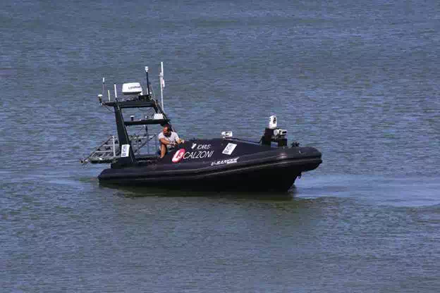
FIGURE 1.
Calzoni U‐Ranger USV (source: ICARUS).
The U‐Ranger can be equipped with different kinds of sensors like cameras and radar for surface area control, sonar sensors for underwater control and other sensors for environment control. Table 1 lists the main technical characteristics of the system.

Within the scope of the ICARUS project, the U‐Ranger USV was equipped with a sensor and autonomous behaviour payload from Centre for Maritime Research and Experimentation (CMRE). The autonomous behaviour payload is based on the mission oriented operating suite (MOOS) open‐source open architecture. The MOOS is a C++ cross platform middleware for robotics research. Its advantages include open source, flexibility, capacity for system growth, functionality across all platforms, a large user community who contribute MOOS architecture modules for all to share, scalability through distributed computation, protocols exist and need not be developed and considerable use in autonomous systems internationally, at CMRE and elsewhere. MOOS interacts with hardware and operator GUI through MOOS interface drivers and MOOS processes (autonomous behaviour sets), each of which is an independent process linked to a central MOOS database by standard internal process connections. Processes post data to the central MOOS database for access by any other process. Processes subscribe to the data they require, drawing it from the MOOS database on notification of updates. Communications between the sensor/behaviour payload and the control station on‐shore rely on a worldwide interoperability for microwave access (WiMAX) link, while the very high frequency (VHF) link bypasses the sensor/behaviour payload allowing direct full manual control of the USV.
The sensor suite includes the following sensors:
● RADAR: Obstacle detection
● Laser scanner: Obstacle detection
● Weather station: In Situ weather data
● Daylight camera: Survivors detection
● Thermal camera: Survivors detection
The thermal and daylight cameras allow night and day operations. Their fields of view and resolutions are such that it is possible to detect a person in the water at 200 m. While the daylight camera is quite sensitive to lightning conditions and in particular to the reflections of sun light on the water surface, the thermal camera can provide useful data almost independently of the environmental conditions. An example of an image provided by this camera can be observed in Figure 2. Furthermore, the cameras are mounted on a gyro‐stabilized platform that also allows their pan and tilt command.

FIGURE 2.
Example image from the thermal camera on the U‐Ranger (source: ICARUS).
The radar installed on the U‐Ranger operates on the X‐Band (9.3–9.4 GHz) and can be configured with different range settings from 50 m to 24 nautical miles. It has a rotation rate of 24 RPM and it is interfaced to the computational system using public domain C++/Java plugins/libraries (openCPN BR24 plugin and openbr24 Java). This radar is able to reliably detect obstacles at ranges greater than 50–100 m. The major drawback is the difficulty in detecting fast objects or making detections during sharp turns of the U‐Ranger.
The laser scanner has four vertically stacked beams with a spacing of 0.8°, which are steered within a 110° angle and with 0.125° horizontal resolution. The maximum scanning frequency is 50 Hz and the obstacle detection range is greater than 100 m. This scanner is mounted near the U‐Ranger bow on a gyro‐stabilized platform (Figure 3).

FIGURE 3.
Laser scanner mounting platform and electronics (source: ICARUS).
The behaviour set implemented in the U‐Ranger MOOS system contains the following elements:
● Constant speed
○ Classic part of the MOOS‐IvP and always active.
● Station keeping
○ U-Ranger vehicle is not able to stop in an autonomous mode.
○ Vehicle with a single thruster and rudder.
○ Last waypoint is always considered as a station keeping point.
● Waypoint behaviour
○ Selection of waypoints is the C2I operator responsibility.
○ Any waypoint can be selected as the U‐CAP deployment point except the last one..
● Operational region
○ Pre‐defined operational area polygon.
● Obstacle avoidance
The available behaviours are combined in real time by a function optimizer in order to determine the direction the USV should take.
Roaz II USV
Roaz II is an USV that can operate in full autonomous mode or remotely operated from a base station. It can be configured to carry different sets of sensors and to perform several kinds of missions, including environmental monitoring, harbour protection or bathymetric data gathering. Its main characteristics are described in Table 2.

Roaz II is operated from a mission control station composed by a ruggedized computer and a set of auxiliary devices including antennas. It is capable of executing autonomous missions defined by a list of waypoints differential GPS system and an inertial measurement unit. Telemetry as well as payload data are transmitted in real time to the mission control station.
For navigation purposes, the vehicle uses a precision L1/L2 GPS receiver (Septentrio PolaRx2) and an inertial motion unit (Microstrain 3DM‐GX1) providing attitude information. Propulsion is achieved through the use of two 2 kW electric thrusters with the vehicle reaching a maximum speed of 10 kts. A set of LiFePo batteries provides up to 8 h of autonomy. Communications with the control station are provided by a WiFi link, allowing remote control, autonomous mission supervision and also transmission of telemetry and payload data to shore.
Although this USV does not fulfil all the requirements for search and rescue (SAR) operations as defined in the ICARUS project (mainly the ones related to maximum speed and range) and its adaptation would require a great effort, its characteristics make it a valuable asset in many experiments as well as in the final demonstration scenario.
For that purpose, a thermal camera, a visible camera as well as a radar similar to the one integrated in the U‐Ranger were also integrated in Roaz II (Figure 4).
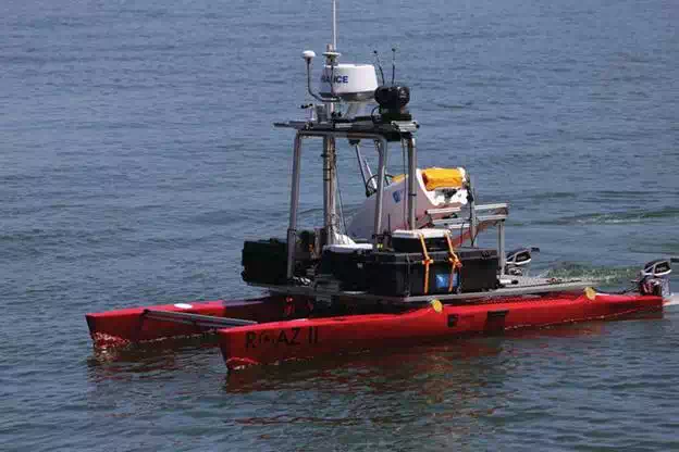
FIGURE 4.
Roaz II USV (source: ICARUS).
Unmanned capsule
The UCAP (Figure 5) is a single hull vessel, with a lower rear deck to accommodate the uninflated life raft as well as the corresponding compressed gas bottle. The hull was fabricated in fibreglass, using as custom‐made mould.

FIGURE 5.
Unmanned capsule (source: ICARUS).
The UCAP dimension is 1.45 m (length) × 0.52 m (width) × 0.42 m (maximum height). It weighs 22 kg and has a payload capacity exceeding 15 kg.
A jet drive unit assures the propulsion of the UCAP. This jet drive unit is attached to a brushless motor and is capable of delivering a maximum force of 80 N with a power consumption of 800 W. This maximum thrust assures a top speed greater than 5 kts.
On‐board energy is provided by two packs of ZIPPY Flightmax 5000 mAh 6S1P LiPo batteries. This solution assures about 220 Wh of total on‐board energy. Taking into account the efficiency of the propulsion system, the continuous operation at 1.5 m/s (3 kts) for 20 min (resulting in range of 2 km) should require about 100 Wh of energy, leaving 120 Wh for electronics and communications, which consume about 10 Wh. The battery pack is enclosed in a watertight box that is located in the bow compartment. This compartment also houses another watertight box with the on‐board computer, navigation sensors and communications equipment. The bow compartment is also watertight assuring a double protection for electronics and batteries.
Navigation sensors include a PNI Trax AHRS and an Ublox Neo 6P GPS. Trax AHRS is a low‐power and low‐cost attitude and heading reference system with a static heading accuracy of 0.2° and an overall accuracy better than 2° in the presence of magnetic distortions. NEO 6P is a low cost GPS receiver that operates at 10 Hz, outputs raw data, being supported by RTKLIB, an open source library that implements differential and real time kinematic corrections using small size and inexpensive receivers.
Communications with a control station are assured by a long‐range Wi‐Fi link that establishes a wide band link over distances above 1 km (depending on height of the shore station antenna over the water surface and on the wave conditions).
A video camera is also installed on the UCAP. A video stream is fed to the control station for possible assessment of victim conditions when the UCAP is close to them, as show in Figure 6.
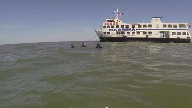
FIGURE 6.
Image taken from the unmanned capsule on‐board camera (source: ICARUS).
Besides the described items, on‐board electronics also includes a load balancing and protection system for the batteries, the motor controllers or the water jet motor and direction servo as well as triggering systems for the inflation of the raft. The interconnections between all on‐board systems are depicted in Figure 7.

FIGURE 7.
System architecture—electronics (source: ICARUS).
The on‐board software is composed of several modules that communicate with each other using a message passing mechanism as shown in Figure 8.

FIGURE 8.
System architecture—software (source: ICARUS).
These modules follow a hierarchical architecture similar to the one used in the other INESC TEC robotic systems. At the lowest level, the modules that interact directly with the sensors and actuation devices constitute a hardware abstraction layer. On top of these, two major modules are responsible for the navigation (real time estimation of the UCAP position, velocity and attitude) and for the control (execution of manoeuvres and other high level behaviours).
The navigation module processes data from the GPS and inertial measurement unit (IMU) systems. The GPS system provides the information about location and velocity. The IMU has incorporated magnetometers, accelerometers and gyroscopes, providing information about yaw, pitch and roll states, acceleration and rotational movements decomposed. A data fusion algorithm is used to estimate the position of the capsule whenever the GPS receiver loses track, possibly due to excessive roll or pitch caused by stronger waves. At the same time, the inertial data are used to obtain updated information on the external disturbances, allowing a better characterization of the navigation environment.
The UCAP carries a lightweight life raft as the one presented in Figure 9. This life raft weights 8 kg (raft + full inflation bottle) and the overall volume before inflation is 13 dm3.

FIGURE 9.
Inflated life raft (source: ICARUS).
A mobile computer running software for real‐time monitoring and control of unmanned capsules composes the operation console. A graphical interface (Figure 10) provides the operator with the most relevant data concerning the state of a UCAP and allows him to control its operation. A joystick can be optionally connected to the computer to simplify the interaction with the UCAP.
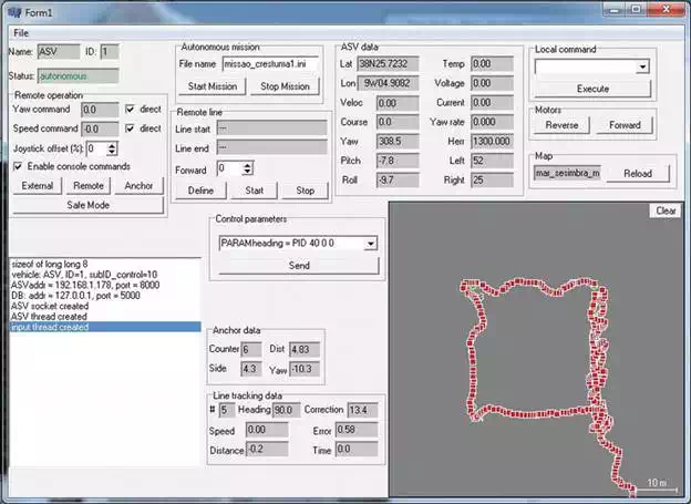
FIGURE 10.
UCAP operation console (source: ICARUS).
This console allows the operator to switch between different UCAP operating modes:
1. Idle mode: where the UCAP actuation is shut down, causing it to drift according to external disturbances (winds and currents).
2. Anchor mode: that allows performing station keeping, where the UCAP will loiter compensating drifts caused by winds, currents or other influences.
3. Waypoint navigation mode: which consists of autonomous operation of the UCAP following a sequence of waypoints defined by the operator or imported from a previously defined file.
4. Remote control mode: where the operator remotely controls the UCAP.
5. External mode: which consists of granting the control of the UCAP to an external entity. This mode is similar to the idle mode except that another entity (for example the ICARUS C2I) can take control of the vehicle.
Specific information about the UCAP that is displayed in the graphical interface includes
● Velocity
● Position
● Attitude (heading, pitch and yaw)
● Actuation (thrust and direction commands)
● Battery level
● Real‐time power consumption and estimated endurance
When the UCAP is in autonomous operation, further information concerning the status of such operation (distance to next waypoint, estimated time no next waypoint completion or distance to anchor point in anchor mode) is also provided to the operator.
A heartbeat mechanism is implemented between the UCAPs and operator console to support emergency behaviour of the UCAP in case of communication link failure.
Unmanned capsule deployment system
The deployment system consists of a mechanical structure and a release system that could be easily modified or redesigned to suit several carrier USVs (Figure 11). The structure consists of a ramp that allows the gravity to be the main force imposing forward motion to the UCAP during launch. It is made of anodized aluminium bars to keep the overall weight low and resist to corrosion due to salt water. When placed on the launching ramp, the UCAP sits on rubber rollers that allow the movement in the forward direction while constraining it in the transversal direction.
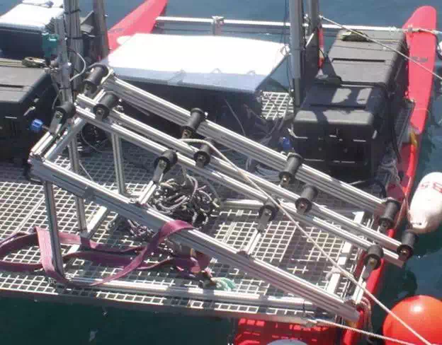
FIGURE 11.
UCAP deployment system installed on Roaz II USV (source: ICARUS).
The release system is composed by an electric latching device and an electronic system required for its command. This system is housed in a watertight box and is composed by a microcontroller, a power amplifier and a battery. The system is connected to the carrier USV communications infrastructure so that it can receive a remote command to release the UCAP. This command can be issued by a command line or a graphical interface running on any Linux‐based device.
The deployment system can be easily integrated on a carrier USV (Figure 12), requiring only the following operations:
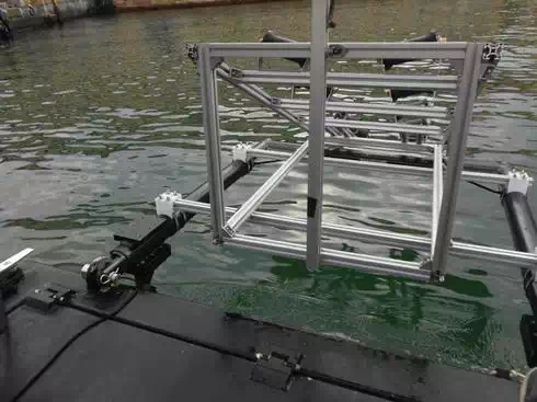
FIGURE 12.
Deployment system installed on the U‐RANGER USV (source: ICARUS).
● Mechanical integration of the ramp
● Connection of the electronics box to the USV communications network
● Configuration of the microcontroller to use the carrier USV communications network
Mounting the UCAP on the deployment system is a simple operation that can be performed, whereas the carrier USV is moored next to pier (Figure 13). The UCAP can be directly mounted on the rollers on ramp with the help of a rubber boat.
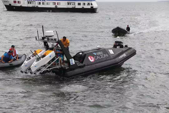
FIGURE 13.
Two UCAPs mounted on the deployment system installed on the U‐RANGER (source: ICARUS).
Upon mounting the UCAP on the ramp, it must be secured to the release mechanism. For that purpose, a rope with a metal attached to it is fastened to the stern of the UCAP; and when the UCAP is in place, that pin is attached to the latching device.
Afterwards, for releasing the UCAP, a simple command needs to be sent to microcontroller in the electronic box of the deployment system (Figure 14).
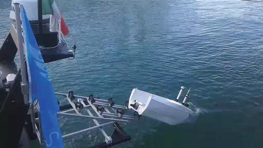
FIGURE 14.
UCAP being launched from the U‐RANGER (source: ICARUS).
Conclusions
This chapter addresses the work performed within the scope of the ICARUS project on the development of complementary unmanned maritime systems technologies for search and rescue. This work aimed at delivering a set of tools that can act not only as a part of the ICARUS toolset, but can also be used independently. For one side, such developments consisted in endowing medium and large scale unmanned surface vehicles with augmented perception and autonomic capabilities so that they could perform search and rescue operations in complex environments with the presence of other vessels and victims on the water, reporting back to the control stations situational awareness information. On the other hand, the concept of unmanned capsule, which is a small‐size platform able to carry a life raft and inflate it close to victims, was prototyped, and integration as payload of larger unmanned platforms was also addressed. These developments and their extensive validation in several field trials and demonstrations carried out along the project are therefore a relevant contribution for the real‐world deployment of robotics platforms in search and rescue operations, complementing the operation of traditional search and rescue teams.