Unmanned Ground Robots for Rescue Tasks
Ground robots have demonstrated to be a useful tool when dealing with post-disasters intervention and in particular for Urban Search and Rescue (USAR).
From the experience of the search and rescue (SAR) operators that have been consulted, it came out as the best ground robot for SAR operations would have such large variety of capabilities and tools that it would not be feasible to merge in a single machine. Hence, the strategy to use two different robots with well-defined and complementary capabilities:
● A large unmanned ground vehicle (UGV) to perform heavy duty jobs and collect information about dangerous places
● A small UGV to enter tight places, look for victims, and provide indoor view for danger assessment
These two robots can be either used together within one SAR team to have the most effectiveness or can be used independently of each other.
The advantages of using UGVs in disaster scenarios are multiple:
● Faster location of victims
● Shorter rescue times
● Less risk for the SAR operators
● Faster assessment of damage to buildings
The disadvantage to have two machines to develop instead of a single one can be partially compensated using similar structures and control programs on both robots.
STATE OF THE ART
Kleiner addresses the problems of robot localization, environment mapping, team coordination, and victim detection. In particular, an RFID-SLAM approach is used to close the loop when mapping. Robot and human’s position is tracked respectively by slippage-sensitive odometry and pedestrian dead reckoning (PDR). Maps are then used for both centralized and decentralized coordination of rescue teams. Data collected by robots are available to SAR operators through wearable devices like head-mounted display (HMD).
Michael combines maps generated by an unmanned aerial vehicle (UAV) and a ground robot used as a moving base. The cooperation between UGV and UAV in particular is addressed. The purpose is to explore compromised nuclear power plants that are too risky for humans due to the high level of radioactivity. Maps are generated from 3D sensor data using the Iterative Closest Point (ICP) approach. Maps are then corrected based on the odometry readings.
Murphy focuses on robots for underground mine rescue. The physical challenges emerging from different scenarios are addressed and different platforms are proposed to better fit the various scenarios. In particular, most of the platforms proposed are mobile robots equipped with tracks and a dexterous manipulator and they are teleoperated through fibre-optic cable.
In the Viewfinder Project, robotic tools were developed for disaster management and for supporting fire-fighting services. However, the project concentrated mostly on developing the teleoperation and autonomous navigation capabilities and did not consider the mobility of the unmanned vehicles on rough terrain. This dichotomy is often seen in research projects: either they concentrate on conducting research on robot mobility in rough terrain or either on increasing the cognitive/intelligent behaviour of the robotic assets, but seldom on the combination of both research domains.
In the EU-funded project NIFTi, a system for supporting human-robot teams during disaster response has been designed and developed. A UGV is used in different scenarios to explore the disaster area and look for victims. In a similar way as the ICARUS SUGV, the NIFTi UGV has some capabilities necessary to accomplish the USAR missions:
● Automatic victim detection
● Creation of metrical map based on LIDAR
● Path planning
● Multimodal human-robot interaction
Furthermore, the NIFTi UGV has some higher-level features that make it able to reason and infer more complex concepts about the environment.
The localization is performed fusing visual and inertial odometry and correcting the result with an estimate obtained through the ICP algorithm.
The high level representation of the sensory inputs is addressed using a topological representation of the environment consisting in a graph whose nodes can be either relevant objects or regions obtained by segmentation of the metric map. The robot uses this representation to autonomously plan a method to execute a task.
The EU-funded project TRADR is a sequel to the aforementioned project NIFTi. After the earthquake in Amatrice, Italy, deployment with a teleoperated UGV and some UAVs has been performed. The UGV carries similar sensors as the ICARUS SUGV, with the exception that the former has a LadyBug3 omnidirectional camera while on the SUGV it has been preferred to mount single cameras in the most critical points. The laser scanner is almost the same model, but in the TRADR UGV, it is mounted on the front on a rotating unit, to provide a 3D point cloud, while on the SUGV, the two laser scanners are fixed on the sides and the 3D point cloud is provided by a time-of-flight camera.
SUBTASKS
Breaking with the tradition of focusing on only one research domain, the ICARUS project developed intelligent robotic agents with high mobility on rough terrain. The UGVs represent, within the ICARUS project, the core of the assistive robots during land disasters like earthquakes, floods, landslides, etc. The UGVs are not meant to be a substitute of human search and rescue operators but they are instead a complementary tool to assist them and extend their operational possibilities.
The large unmanned ground vehicle (LUGV) is intended to be primarily a means to open the way to rescuers whenever the way is obstructed by debris. The possibility to mount the jackhammer makes it useful to break with a certain speed walls and concrete slabs. Using the gripper then makes it possible to remove debris and stones that obstruct the entrance to a damaged building. Whenever the structure of the building is not completely stable, it is possible to use the gripper to place some struts to stabilize it; in this way, the risk for the rescuers is minimal as they can perform this operation remotely.
When the entrance to the collapsed building is large enough to allow the passage of the small unmanned ground vehicle (SUGV), then its box is hooked to the end-effector of LUGV arm and it is deployed. If the ground floor is still not accessible, it is possible to deploy SUGV on a balcony or a roof up to 3 m.
The SUGV can explore the inside of a building, teleoperated from a remote area. The operator has a view of the environment around the robot, thanks to the numerous sensors and the mapping system. Knowledge of the obstacles that are near the robot is necessary when doing manoeuvres in tight space in order to avoid collisions that could make the robot unusable.
With an infrared camera, SUGV is able to find heat traces belonging to victims that cannot move. When a victim is found then the operator can annotate its position and deliver a small rescue kit like water or oxygen. When the communication bandwidth is enough, bidirectional voice communication with the victim is possible in order to give instructions and to reassure the victim.
Mechatronics of the large unmanned ground vehicle
DESIGN CONCEPT
The LUGV (Figure 1) was originally a commercial vehicle built by the French company Metalliance. It was adapted to the purposes of ICARUS project and provided to the University of Kaiserslautern. Its specifications are shown in Table 1. The main power is provided by a diesel engine which in turn actuates a hydraulic pump. This latter pumps oil into the pistons that actuate the two tracks. A turbine attached to a generator is actuated by the oil flow as well and this latter provides 220 V AC.

FIGURE 1.
Large unmanned ground vehicle (Source: ICARUS).
LUGV has a high mobility on uneven terrain due to its big caterpillars that allow in-place rotations as well. A 5 degree of freedom hydraulically actuated manipulator is mounted on top of the vehicle. Different tools can be attached to the end-effector, a gripper, a jackhammer, or a box to transport the SUGV.
The control program runs on a PC that communicates with a PLC, this latter deals directly with the low level hardware. The manipulator has its own controllers that are connected to the main PC.
SENSOR SYSTEM
The position and orientation on LUGV are provided respectively by a global navigation satellite system (GNSS) and an inertial measurement unit (IMU). As there is quite some space on the LUGV, it has been possible to mount two GNSS antennas, making the position measurement more precise.
A stereo-camera system was mounted on the front section bar tower, with the aim of providing a dense 3D point cloud used for mapping and obstacle detection. The choice of the stereo-camera system is justified by a bigger range with respect to a time-of-flight camera. One camera of the stereo-system is used also as direct visual feedback by the remote operator. Since this camera is attached to the main structure of the robot, an IP camera is mounted on the arm next to the elbow joint, which provides visibility about the arm in order to not hit any object during manipulation activities. Finally, a USB webcam was installed on the end-effector to have direct visibility on the tool.
Two laser range finders are mounted on the front and the rear side for obstacle detection, in a similar fashion as on SUGV but the sensor type on LUGV has a bigger range and a smaller resolution; further details are shown in Section 6.1.
MECHATRONICS OF THE ARM
The LUGV manipulator is a 5 degree of freedom arm, which is hydraulically actuated. The workspace of the manipulator is shown in Figure 2.
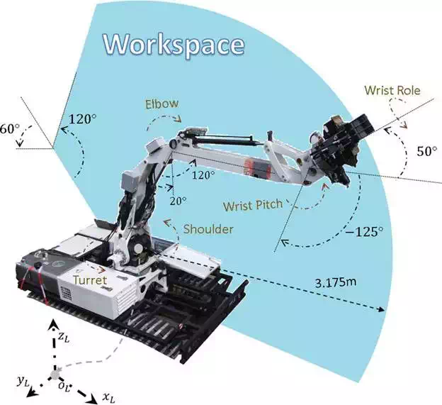
FIGURE 2.
Workspace for the manipulator arm on the LUGV (Source: ICARUS).
A simple PID controller is used to control the joint angles. During operation, the temperature and pressure of the hydraulic oil is changing and therefore the internal dynamics of the hydraulic actuator is time variant. This can result in undesirable oscillations if the PID controller is set to high gains. The issue of stability can be alleviated by reducing the PID gains and consequently decreasing the precision. Due to the safety issues of such a large vehicle, the PID controller has to be chosen in low gain to guarantee stability. We adopted a different methodology to overcome the problem of stability. In order to increase the speed of operation and precision, a virtual trajectory was calculated to force the arm towards the desired trajectory; nevertheless, this method had no benefit in remote control scenario where the user directly moves the manipulator. Our experiments proved that for convenient operation of the arm a haptic controller with force feedback is necessary to safely control such a highly dynamic arm.
The LUGV manipulator was equipped with three different tools. The gripper tool is used for grabbing and moving obstacles such as metal sheets, bricks, etc. The controller provides satisfactory accuracy for grasping task. The other tool is jackhammer. This tool is used to breach the concrete walls and in several demonstrations proved to be a useful way for the SUGV to enter hazardous buildings. SUGV box is another tool that is used to carry and deploy SUGV near the rescue area. Deploying SUGV is vital to the rescue operation since SUGV can cover a maximum radius of 50 m in a reasonable time. Where LUGV can approach the building, it can save the battery power of the SUGV for more indoor operation. LUGV also has the capability of deploying SUGV up to 3 m above the ground, and this provides flexibility to the rescue operation where SUGV can be directly placed on the first floor of a building.
Mechatronics of the small unmanned ground vehicle
DESIGN CONCEPT
The SUGV (Figure 3) is a commercial robot originally produced by the British company Allen Vanguard as a teleoperated robot for bomb defusing. The specifications of the system are shown in Table 2.

FIGURE 3.
Small unmanned ground vehicle (Source: ICARUS).

The platform motion is provided by two tracks actuated by an electric motor with a gearbox. The tracks are a bit higher in the front side, and this permits to climb steps up to 20 cm.
The 5 degree of freedom manipulator allows to open doors, grasp small objects, or extend the visual feedback where the platform cannot arrive, like through small holes or above little walls. Each joint of the arm is actuated by a DC motor and a worm gearbox.
The low-level control of the caterpillar motors and the manipulator is performed by a dedicated motor controller and a digital signal processor (DSP), respectively. The DSP is in charge also to control the lights and gather information from the joint encoders. The main processing power is provided by a PC mounted on the rear part of the chassis. It is present as a second processing unit in an Odroid, which is used only to collect data from some sensors.
SENSOR SYSTEM
The SUGV was provided with a rich sensor configuration for the purpose of ICARUS:
● An IMU and GPS provide basic telemetry like position and orientation.
● A Kinect of the second generation is installed in the front part of the chassis. It provides a dense 3D point cloud used for navigation and obstacle avoidance. Two laser range finders (LRF) are mounted on both sides for the same purpose. Two different maps are built from the Kinect and LRF and then merged together afterwards (Section 6.1).
● An RGB camera is integrated into the Kinect, while a second camera is installed on the gripper and is used when it is needed to grasp objects with the manipulator or when it is necessary to extend the visual feedback to places that are inaccessible for the whole robot, like below furniture, or inside small holes. A third RGB camera is mounted on the rear side. It is set to a low resolution to reduce the network load. This camera is used mainly when doing manoeuvres in tight space where rear vision is required.
● An infrared camera with a quantum cascade detector were mounted after the demonstrations to find the heat trace of alive victims as well as the presence of CO2 in the air.
● As requested by the end-users, a CO2 sensor was installed to measure CO2 in the air with direct contact.
● A microphone and speaker were mounted as well to allow a direct communication with victims when possible or text-based messages when the communication bandwidth is low.
MECHATRONICS OF THE ARM
The SUGV manipulator (Figure 4) has three rotational joints on the arm and two rotational joints on the wrist. It is able to perform the required tasks inside its workspace. The arm is designed to perform low speed high precision object manipulation, where its actuators are equipped with worm drive gear-boxes to maximize the load capability of the arm and reduce the negative effect of the load disturbance on position control. Henceforth, the arm is capable to lift up to 20 kg weight in compact mode and 8 kg in fully stretched mode.

FIGURE 4.
The workspace of the SUGV manipulator (Source: ICARUS).
The joints are using magnetic absolute encoders that are resistant to dust and moisture with a resolution of 0.1 degree. The sensory feedback provides high precision position control which is only limited with the backlash of the drive boxes. This feedback can also be applied to provide force feedback for the haptic device. Our experiment demonstrated that the force feedback calculated based on position error can help the user to have a better understanding of the motion and adapt itself to the slow speed of the manipulator. The force feedback can be influential in teleoperation with high vision delay. In teleoperation tasks, especially in disaster area, the communication bandwidth is low and the video quality is not good. In such a situation, the force feedback could be of great value since it provides the user fast response from environment preferred to the delayed camera image.
Control concept
On both robots, FINROC (Framework for INtelligent RObot Control) is installed, a C++/Java framework developed by RRLab explicitly to control robots in an easy and flexible way.
The modularity of FINROC allows the user to add modules that perform different tasks and communicate with each other through ports. The user does not have to care about details like scheduling, data exchange, or multithreading, as they are managed in the background by the framework. The data type that can be passed through ports can be various, such as values, images, point clouds, etc. The basic requirement is that data must be serializable to be passed.
Two Java-based tools can be used to monitor the program: Finstruct and Fingui. The first shows a tree with the modules that are running within the program and allows the user to connect the ports manually in runtime without the need to recompile; this feature is particularly useful when doing tests on the field and it is required to do fast changes to the program. Fingui is a graphical interface that allows to visualize the output of some ports and to give inputs to others using some predefined graphic widgets.
The structure of the software running on our UGVs has at the top level the graphical interface or the Joypad; both can be used by the operator to provide control inputs (Figure 5).

FIGURE 5.
Control structure (Source: ICARUS).
Such controls are then processed by the control program (IcarusControl) and converted to hardware commands. The control program is in charge of the high level processing of data coming from the sensors. The mapping, localization, navigation, and obstacle avoidance are tasks performed by modules of this layer.
The motion commands for both platform and manipulator are sent by the Hardware Abstraction Layer (HAL) to the related hardware. The HAL is responsible also for collecting data from hardware peripherals such as manipulator encoders and send it to the control program.
Since FINROC is not a ROS node, it could not be directly connected to the ICARUS Command and Control interface (C2I), which is ROS-based. For this purpose, an interface was created using the JAUS (Joint Architecture for Unmanned Systems) library.
On the robot, the interface is a FINROC module that acts as a bidirectional gate: on one side, it receives commands from the C2I to be sent to the robots. On the other side, the interface receives sensor data from the robot and sends them to the C2I. The available data that are sent through the interface in both directions is shown in Table 3.
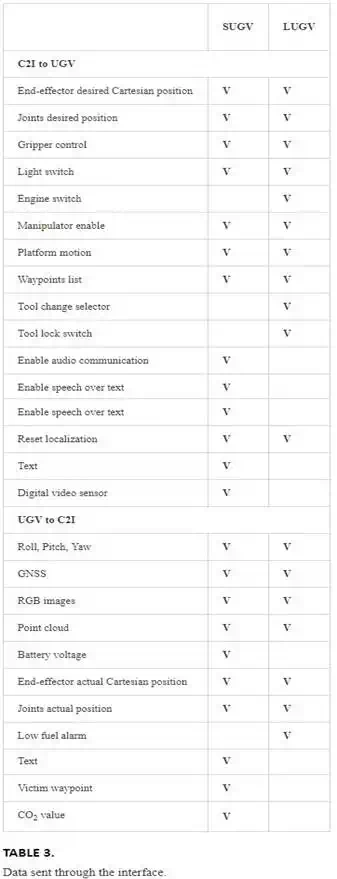
An asynchronous call-back function is called whenever a message is received by the C2I. Depending on the type of the message that is received, the call-back converts it to the proper FINROC-compatible data format and forwards the data to the main control program. At every cycle of the frame the interface gets the input data from the robot and after proper conversion to JAUS formats calls the relative function to forward the data to the JAUS layer.
Simulation
Simulation has been a valuable tool to develop both robots, as shown in Figures 6 and 7. Because of the difficulty and the costs, both in time and money, to test the platforms (the LUGV in particular), some simulations were created using different simulation engines.

FIGURE 6.
SUGV simulation (Source: ICARUS).

FIGURE 7.
LUGV simulation (Source: ICARUS).
The last and most accurate simulation performed makes use of the Virtual-Robot Experimentation Platform (V-REP).
A CAD model of both robots has been drawn, part-by-part, and then assembled in the simulation and provided with dynamic properties measured on the real robots, such as mass, moment of inertia, centre of mass, and friction coefficient.
In the simulation, the robot’s hardware is replaced by a physical model of the real platforms. The higher level control program used to control the simulated robots is the same that is used to control the real robots.
Simulation has been particularly useful to test the collision avoidance system, for which a big space with many different obstacles was necessary.
Navigation of the UGVs in an unstructured environment
MAPPING
A proper mapping system is available on both robots. It processes the information about the environment gathered by the sensors and it converts to a format that is usable by the collision avoidance system and by the human operator. This system is composed of the following parts:
● Laser range finders (LRF) + stereo-camera (LUGV only)
● Grid map
● Sector map
On the LUGV, two LRFs are installed, one in the front and one in the back. Both are attached to a section bar structure fixed directly to the bumpers. The sensor is a SICk LMS511, a planar laser scanner protected by a case against rain and dust. The scan has a horizontal field of view (FOV) of 180°, the scan range is about 80 m, for a minimum angular resolution of 1/6°. Sensor frequency is set to 10 Hz, which means that 10 scans per each device are done in a second and each scan provides 1080 planar points. The height of the sensors is about one-half of the track height, so that if an obstacle intersects the scan plane it is considered not traversable, everything that lies below the scan plane is considered traversable. Both laser scanners are not completely outside the vehicle but they are protected by its bumpers in such a way that if the obstacle detection fails and an obstacle is hit, the first part to hit is the bumper instead of the more delicate and expensive laser scanner. Anyway a suitable position is found considering also the needing to have the least possible parts belonging to the vehicle that obstruct the FOV of the sensor.
On the SUGV, two LRFs are installed as well. Smaller than the ones mounted on LUGV, they are located on both sides, with the plane of scan just above the tracks. Even if the FOV of this scanner type is 270°, they are limited to 180° to avoid that parts of the robot itself fall within the FOV. The scan range is 10 m and the minimum angular resolution is 1/3°.
At every cycle both scans from the two devices are merged together and converted from the sensor 2D reference frame to the vehicle 3D reference frame, in this way a 3D point cloud is obtained.
A traversability map is built out of the point cloud. This map is a 2D grid of cells built around the vehicle, and sizes are by default 20 m × 20 m with a resolution of 0.25 m for LUGV and 6 m × 6 m with a resolution of 0.05 m for SUGV.
In the pre-processing phase, the point cloud is filtered and the points too close to the sensor are removed because they are assumed to belong to the robot itself. The point cloud is then filled into the grid map. For each point belonging to the cloud, the corresponding cell in the map is found. Each cell keeps a count of how many points lie inside it.
To consider a cell as an obstacle, it is necessary that the number of points contained is more than a specific threshold. Such threshold is not constant for all cells but it is inversely proportional to the radial distance from the vehicle; this is done to keep into account that the point density decreases in far cells.
A cell can have on of the following labels:
● UNKNOWN: if the cell is out of the FOV of the sensors and it was never explored
● FREE: if it is within the FOV of the sensors and the number of points inside is lower than the threshold
● EXPECTED FREE: if it was FREE in the previous cycle and it is now out of the FOV
● OBSTACLE: if the number of points inside is higher than the threshold
● EXPECTED OBSTACLE: if it was OBSTACLE in the previous cycle and it is now out of the FOV
● ROBOT: are the cells covered by the robot
The meaning of EXPECTED FREE and EXPECTED OBSTACLE is that we have some information about these cells from the previous cycles but they are currently not covered by the sensors, so we expect that the previous information is still valid but we are not sure.
The grid map is refreshed every cycle and it is connected with the vehicle odometry from the inertial measurement unit (IMU). When the robot moves, the map is shifted of an amount depending on the distance travelled by the robot. In this way, the robot is always in the centre of the map and the obstacles shift. If an obstacle goes out of the map boundary its information is lost. If the robot rotates then the virtual robot in the map rotates while the obstacles around are fixed.
The sector map is the next level of the obstacle detection system. It is a local map built out of the grid map. It contains information about the very close distance from the robot.
Two types of maps are used: a Cartesian and a polar map. A total of 18 maps belonging to the two types are used. Each map contains 10 sectors and each sector stores the minimum free range. The purpose of the sector is to know how much manoeuvrability has the robot in order to not collide with any obstacle.
Sector maps are filled from cells of the grid map. In particular, for each OBSTACLE and EXPECTED OBSTACLE cell the distance from each sector origin is performed and if such distance is less than the sector maximum range then the current sector range is set equal to the cell distance. To speed up the processing, only the cells that lie within the FOV of the sensors are computed.
Sector maps are then used to feed the behaviour-based collision avoidance network that is based on this information and on the motion control from operator decides which movement to perform.
Figures 8–10 depict the different stages of the mapping process: evolving from a point cloud to a grid map to end up with a sector map.

FIGURE 8.
2D view of 3D point cloud (Source: ICARUS).
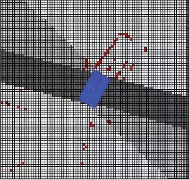
FIGURE 9.
Grid map (Source: ICARUS).

FIGURE 10.
Sector map (Source: ICARUS).
On the SUGV, a further mapping is performed based on a dense 3D point cloud that is gathered by the Kinect. The same process is applied as for the LRFs and the behaviour-based collision avoidance system is in charge to fuse the information from both sector maps (Kinect and LRFs).
PATH PLANNING
The navigation system, further discussed in, is the same on both robots, except some parameters that are strictly platform-dependent. Since both robots have the capability to perform in-place turns, it was preferred to perform a simple point-approach navigator instead of a more complex trajectory tracking.
The difference is that with the point-approach technique a sequence of geographical points must be provided by the user. Starting from where the robot is located as soon as it receives the sequence, it turns in-place towards the first point in the list and it begins moving in a virtual straight line to reach it. When the point is reached, the robot goes on to reach the second point in the list and so on.
The trajectory between two consecutive points is subordinate to the collision avoidance system. That means that the robot tries to move in a straight line but if there are obstacles on its trajectory it performs manoeuvres in order to avoid them and it re-plans a new trajectory to the next point.
To have a correct navigation it is obvious that a precise localization system is correct, in both indoor and outdoor environments.
Control of the manipulator arm
The control loop of the manipulator is illustrated in the Figure 11. The lower level of the controller is a digital signal processing (DSP) unit, responsible to calculate and acquire the sensor data to control the position of the joints. It also uses the CAN Bus interface to send the sensory data to the onboard computer where the higher level calculations such as inverse and forward kinematics are performed. The electronics are designed very flexible since many different features and I/O interfaces can be added to the system later on. For instance, touch sensors are added to the gripper later on to give the force feedback of the contact force. Also, laser pointer with circular pattern was added to give better sense of distance to the user. Different lights and analogue sensors could be extended due to versatile design of the electronics.
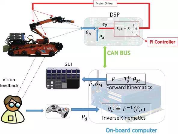
FIGURE 11.
The control loop of the manipulator arm (Source: ICARUS).
The onboard computer calculates the kinematics and assists the user in control. Based on the experiments, four different control modes are coded for user interface. In workspace mode, the user is able to control the velocity of the manipulator with respect to robot frame. This mode is useful when the user has a direct eye contact with the robot, without using an onboard camera. The configuration mode gives the user possibility to control each joint. This mode is for test and calibration of the manipulator and is not recommended for manipulation task. In the camera mode, the user is controlling the speed of the tool centre point (TCP) with respect to camera frame placed on the end effector. The last mode is Pose mode, where instead of velocity, directly the desired workspace position and orientation (Pd) of the TCP is commanded by the user. This mode is particularly useful when haptic joysticks or an exoskeleton is used to control the arm. Using this mode, the position and orientation of the user’s hand will be directly mapped to the pose of the manipulator. This makes the manipulation much easier and faster; indeed, complicated tasks without using haptic devices are almost impossible to perform with articulated arm.
Experimental validation
Operational validation trials were performed in Marche en Famenne, Belgium, in order to assess the capabilities of the SUGV and LUGV against the user requirements. On the LUGV, the 3D vision sensor was integrated into the robotic control framework FINROC. After mounting the sensor on the vehicle, a calibration of the sensor (see Figure 12) has been carried out to synchronize the sensor coordinate frame with the robot coordinate frame. Several tests to ensure that the detection of obstacles, the traversability information, and the visual feedback were correctly set up.
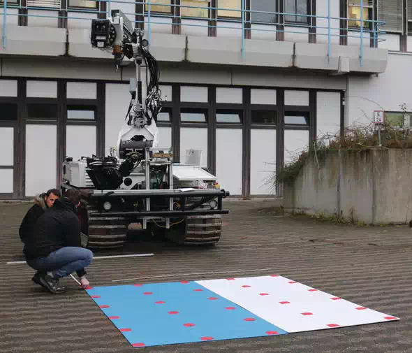
FIGURE 12.
Calibration of the 3D vision sensor. The sensor can be seen mounted on the sensor tower of the LUGV (Source: ICARUS).
Subsequently, the autonomous navigation was evaluated: the vehicle has been given a list of GPS waypoints and it was successfully able to reach them without any direct control. Also, the manipulation capabilities of the LUGV were tested. First, the box with the SUGV inside has been lifted to a height of more than 2 m and the SUGV has been deployed on the roof of a test building (see Figure 13).

FIGURE 13.
The LUGV uses its arm to lift the transport box containing the SUGV (Source: ICARUS).
Before entering the building, a door had to be opened. This was accomplished using the feedback-controlled manipulator arm of the SUGV. Then the vehicle had been driven remotely inside the damaged building using its own lights and a camera to look for victims in all rooms, passing through a hole in the wall and descending stairs (see Figure 14).

FIGURE 14.
Due to its small size, the SUGV is able to drive through narrow openings (Source: ICARUS).
All the available tools have been successfully mounted on LUGV: the box for the SUGV, the gripper, and the jackhammer (see Figure 15). Then some rocks have been grasped with the gripper and a concrete piece has been broken to assess the capabilities of the jackhammer (see Figure 16).
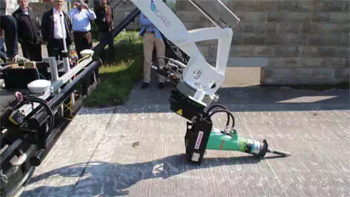
FIGURE 15.
The jackhammer is being attached to the arm of the LUGV (Source: ICARUS).

FIGURE 16.
The LUGV uses its jackhammer to breach through a concrete plate (Source: ICARUS).
Afterward, the small ground vehicle was deployed together with an indoor multi-copter to explore another building.
A posteriori, the human victim detection sensor was integrated on the SUGV (Figure 17). It was mounted next to the arm as this fulfils most of the requirements on the degree of freedom of the manipulator arm, field of view for the human detection sensor, and avoidance of collision-prone configurations.
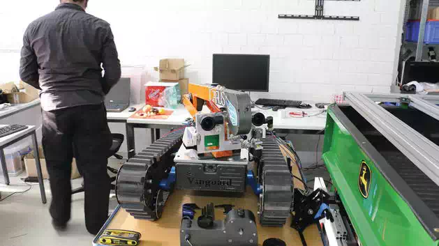
FIGURE 17.
The SUGV with the human detection sensor mounted in front of the manipulator arm (Source: ICARUS).
Main issues and considerations
Various experiments conducted for validation purposes have shown that both UGVs can still be used successfully for search and rescue tasks. The formal validation showed that both the SUGV and LUGV fulfil most of the requirements that have been set out by end users. However, some requirements are currently also not fulfilled and it is important to learn from this. Aspects where more research is required are:
● Compromising system complexity and robustness in large systems, as both systems sometimes had robustness issues.
● Precise manipulation with powerful hydraulic arms, as was not possible to achieve the desired precision with the hydraulic actuator.
● Vibration isolation of sensors, or rendering sensors less prone to noise induced by vibrations.
● Stair climbing of heavily packed robot systems, as the SUGV is capable of climbing stairs, but with the full sensor load, this becomes very difficult for steep stairs designs. A more suitable platform for this task would be equipped with orientable flippers, as it has been done in the EU-funded projects NIFTi and TRADR.
● Long-distance, non–line-of-sight communication for operations inside buildings, as we did still lose communication to the SUGV from time to time.
Conclusions
In this chapter, the ground robots employed in the ICARUS project were described. The LUGV is a heavy-duty supporting machine used to free the way from debris and open a safe passage to the SAR operators. The SUGV is a versatile robot used to explore and search victims within damaged buildings. Both platforms have been described in detail and their advantages and drawbacks related to SAR missions have been addressed. Furthermore, the SUGV has been compared with similar robots used in other projects.
