User-Centered Design
Following the user‐centered design approach, the needs, requirements, and limitations of end users of a product, service, or process are given extensive attention at each stage of the design process. Compared to other product design philosophies, a big difference with the user‐centered design approach is that user‐centered design tries to optimize the product around how users can, want, or need to use the product, instead of trying to force users to change behavior to adapt to the product.
The user‐centered design principles state that designers must analyze and foresee how users are likely to use a product and that they should also test the validity of the initial assumptions with regard to the projected user behavior in real‐world operational tests with actual users at each stage of the design process. The user‐centered design framework can thus be characterized as a multi‐stage problem‐solving iterative design process. Testing and operational validation during each of the stages of the design process (requirements identification, proof of concept development, prototype development, final product development) is absolutely necessary, as it is often very difficult for the designers of a product to understand intuitively what a first‐time user of their design experiences and what each user’s learning curve may look like. In the world of search and rescue (SAR), this requirement for intermediate operational testing is even more important than usual, as the SAR environment is so technology unfriendly due to the harsh operating conditions and the dependence of the human SAR workers on the technological tools at his disposal. This explains why the ICARUS project allocated a lot of effort toward the intermediate operational validation of user needs and expectations via realistic trials and even real‐life deployments, as explained in Section 5 of this chapter.
Next to the benefits in terms of product design quality of following the user‐centered design approach, there is also another key advantage of this paradigm which is of a more social nature and which is often overlooked: user and societal acceptance. Indeed, the acceptance of unmanned tools (such as those developed within the ICARUS project) both by end users and the general society is paramount for the success of the technology. Keeping the end users closely committed is one of the key drivers to increase the acceptance of unmanned search and rescue tools and has therefore been one of the focus points of the ICARUS project.
User identification and requirements gathering
A thorough understanding of the end‐user community is a key preliminary factor in order to be able to define a correct set of end‐user requirements. In the case of ICARUS, the tools are targeted toward the international search and rescue (SAR) community. Within this community, a distinction needs to be made, depending on the terrain where the SAR operations take place, as there exists a separate urban SAR (USAR) and maritime SAR (MSAR) community.
At an international level, the USAR community is organized by the UN via the INSARAG secretariat. INSARAG is a world‐wide network of USAR teams and has developed a standardized set of guidelines and established an external classification (IEC) system for USAR teams. As such, INSARAG provides a single point of entry to access nearly the whole international USAR community.
ICAO and IMO are the international entities that coordinate all MSAR global efforts of their member states. The MSAR system has individual components that must work together to provide the overall service. The global MSAR system operationally relies upon states to establish their national MSAR systems. National MSAR services are then integrated with other states to provide world‐wide coverage.
The USAR and MSAR communities are quite separate. Therefore, it was required to set up separate user requirement gathering approaches specifically targeted toward each of these communities. For both communities, an iterative information gathering approach was followed, where multiple draft documents were compiled, reviewed, and validated by an end‐user board, consisting of members of both the USAR and MSAR communities. Main information sources for these draft documents were personal interviews with key stakeholders, online questionnaires targeted specifically at both communities, and data collected from previous user requirement documents. The draft user requirements were also validated through presentations and discussions at key events where end users were present.
Main user requirement
A complete overview of the user requirements for all ICARUS goes beyond the scope of this chapter. Here, we focus on the requirements that are often disregarded by scientists developing robotic systems.
FAST DEPLOYMENT
Unmanned SAR tools that need to be deployed quickly in remote areas must meet the requirements of air transportability, imposing important constraints on the weight and size of all components. Indeed, goods to be transported over the air must fit inside the cargo bay of standard aircraft used for rescue operations. At the moment of a crisis operation, aircraft cargo space is generally very expensive, as many airplanes are demanded in a short period of time. As such, also the size of the package to be transported must be kept to a minimum. In practice, one can conclude that the whole rescue package should fit on two standard euro‐pallets, which limit the dimensions to 120 cm × 160 cm × 95 cm. This package must not only contain the robotic tools themselves, but evidently also all the tools to repair them. Moreover, the package must not contain any dangerous goods to avoid problems and delays with customs. High‐power batteries, traditionally used for robotic tools, pose a serious problem here, as these are often considered as dangerous goods. Following the INSARAG deployment guidelines, it must be possible to deliver the goods to be transported at the national airport, within 6 hours after getting notice of deployment. Also, important is the total weight of the package, which must of course be brought to a minimum. Realistically, the maximum mass for a package can be estimated at 100 kg. This is the maximum weight for a package, such that two humans can still offload it from a cargo plane. If the mass exceeds this number, then a forklift is necessary, which is often difficult to find in crisis areas.
MANPOWER REQUIREMENTS
SAR teams are always faced with a massive overload of work. Therefore, it is no easy compromise to “sacrifice” people to operate the robotic tools. End users were asked to indicate how many extra team members they could incorporate in their teams for operating unmanned tools. The main conclusion is that no more than two people should be required to operate all the robotic tools.
ENERGY REQUIREMENTS
In disaster areas, one cannot count on the availability of a continuous electrical power supply SAR teams generally need to count on their own power sources. Power generators are mostly used for these purposes, and—more and more—also solar panels. Care must be taken that the unmanned tools do not require more electrical power (e.g., for recharging) than can be given by these power generators. The user survey showed that most teams have access to power generators of up to 2 kVA, so this should be regarded as an upper limit for the electrical power draw.
WATER AND DUST RESISTANCE
Very often, SAR teams are working in dusty and wet conditions. Therefore, also the robotic systems should be dust and water resistant. The end users were asked to indicate the desired level of water resistance for the different unmanned platforms, according to the ingress protection (IP) rating code. As a conclusion of this study, the target IP level for outdoor aerial platforms was set at IP53, whereas ground platforms were rated at IP65 and marine platforms were rated at IP85.
DAYTIME AND NIGHTTIME OPERATION
End users want both ground and aerial systems to be able to operate in total darkness. In the case of USAR operations, this requirement is specifically relevant for all indoor platforms, as—in many cases—USAR operations are paused during the night for security reasons. Some USAR teams report on the other hand that the night would be the ideal time for unmanned interventions, as it is calmer and robotic tools could be less constrained by security problems. For MSAR applications, the possibility of doing operation at night is one of the most relevant features and selling points. The reason is that current (manned) MSAR operations almost always need to be halted overnight due to safety concerns. However, unmanned systems could go on throughout the night and could thereby drastically improve the chances of survival of any victims still in the water.
AUTONOMY REQUIREMENTS
The level of autonomy to be incorporated in the unmanned systems is always a point of much discussion and is a delicate exercise. Many end users report that in practical SAR operations, the unmanned assets will for the foreseeable future need to be teleoperated for safety and legal reasons. This requirement is in contradiction to the request for easy and human friendly control interfaces and high‐level control modalities, which require the incorporation of some degree of autonomy and intelligent autonomous navigation systems. An important factor in this matter is legal issues. Allowing, e.g., unmanned aircraft in civilian airspace is already a sensitive issue in most countries and allowing autonomous aircraft is even more so. Therefore, care must be taken that—at all time—the unmanned aerial platforms can switch to complete teleoperation and act as remotely piloted aircraft (RPA) in order not to limit their deployability in an international context.
SENSING REQUIREMENTS
End users were requested to prioritize the desired sensing modalities to be installed on the different unmanned systems. The results show clearly that end users value the visual contact with victims (via video cameras) and that geo‐referencing of any victims is also deemed to be of high importance. On a second level, infrared and other human detection sensors were selected. On a third level, end users asked for structural 3D mapping capabilities for increasing their situational awareness and also for the presence of a microphone on ground platforms in order to communicate with trapped victims.
COMMUNICATION REQUIREMENTS
In crisis areas, the local communication infrastructure is often damaged and largely dysfunctional. Mail and telephone connections often do not work, and Skype chat is one of the most robust services to keep a conversation. Ad‐hoc communication tools are therefore clearly required.
COMMAND AND CONTROL REQUIREMENTS
Today, there are relatively few hi‐tech tools used in an SAR context. This is mainly due to the fact that the crisis environment is extremely technology unfriendly, and SAR workers are therefore reluctant to introduce new technologies in the field. As the crisis managers are under large amounts of stress to carry out a lot of work in a minimum of time, all technologies they are required to use must be extremely user friendly. This means that simple interfacing technologies should be used, hiding most of the background processing tasks from the user, such that the crisis manager only has to give high‐level (task) commands.
System requirements
Gathering information from the user requirements and the development teams, system requirements and an architecture definition were obtained. The deployment scheme of the ICARUS architecture can be depicted by the scheme of Figure 1.
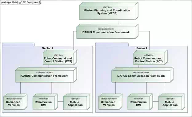
FIGURE 1.
ICARUS deployment architecture (source: ICARUS consortium).
The ICARUS mission planning and coordination system (MPCS) is a system that is deployed at the crisis coordination center and performs the mission planning and coordination activities. Depending on the plan devised at the MPCS, an ICARUS team can perform mission‐level activities commanded directly from the crisis coordination center. In the case of a USAR operation, the INSARAG procedures will be followed and this crisis coordination center will be the on‐site operations and command centre (OSOCC), where also the local emergency management authority (LEMA) and crisis data providers will input their data and mission objectives. In the event of a maritime SAR operation, this central coordination system would be the national maritime rescue and command center (MRCC).
In the case that the disaster is spanning a wider area, the crisis coordination center will generally divide the crisis area into sectors and then assign incoming SAR teams to the sectors based on the team capabilities and any specific sector needs. The number of sectors can vary enormously based on the extent of the crisis, which means that the coordination system must be very flexible to cope with these very different situations. For reasons of clarity, Figure 1 sketches a situation with only two sectors, but the architecture is easily extensible. Following this architecture, each sector receives its own robot command and control station (RC2), which connects via the ICARUS communication framework with the MPCS. This communication link will inevitably have to deal with constraints on the amount of data that can be sent over the wireless communication link. The robot operator uses the robot command and control station to control the multiple ICARUS robotic vehicles via the ICARUS communication framework. Some of the ICARUS vehicles are equipped with a robot‐victim Human-Machine Interface (HMI) system, enabling disaster victims to send feedback (voice, video) to the RC2, thereby enabling bi‐directional communication. At the command station, the local emergency management authority and the crisis data providers and crisis stakeholders interact with the MPCS to input data, enabling the SAR mission planner to assign tasks and missions to the different ICARUS tools via the MPCS. In the field, SAR field teams and first responders are assisted by the ICARUS robots to search for victims and to rescue them. The SAR workers have mobile devices at their disposal, running mobile applications allowing them to read the robot sensor data via the ICARUS communication network and also to contact the RC2 for requesting a change in tasking for the robots.
Definition of operational validation scenarios
Tools that need to be used by end users in difficult operating conditions need to be validated in a test environment which resembles as much as possible the real‐life conditions. It is therefore of the foremost importance that the validation methodology of the robotic search and rescue tools is in line with the real application scenarios as experienced by the end users. To fill this requirement, end users and platform and tool developers together defined a set of use cases for all the tools. A standardized methodology for use‐case redaction was followed, which led to a number of use cases. These were then later refined and transformed into validation scenarios. During this process, end users and platform developers were kept in the loop in order to ensure that the proposed scenarios correspond to realistic platform or tool capabilities and to realistic operational conditions.
The approach followed for conceptualizing the validation scenarios was inspired by the approach developed by the National Institute for Standards and Technology (NIST) for developing standardized test methodologies for unmanned ground robots. In this context, each of the validation scenarios consists of three aspects: a detailed scenario, a capability score sheet, and a score sheet for the different metrics (key performance indicators). This makes it possible to qualitatively and quantitatively evaluate the performance of the different tools during the demonstrations.
All scenarios are ordered chronologically, as depicted in Figure 2 and, when played one after another, form a consistent timeline in line with the demonstration scenarios. Hereby, the leftmost scenario timeline in Figure 2 corresponds to the USAR demonstration scenario, whereas the rightmost scenario timeline in Figure 3 corresponds to MSAR demonstration scenario.

FIGURE 2.
Structure of the different validation scenarios (source: ICARUS consortium).
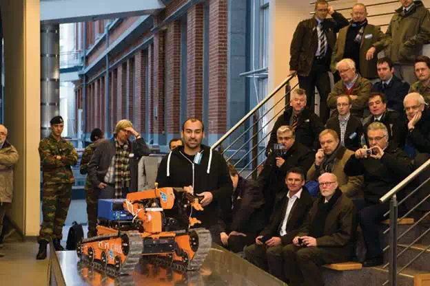
FIGURE 3.
ICARUS small unmanned ground vehicle demonstrated during the first European unmanned search and rescue end users’ conference (source: ICARUS consortium).
Each of these operational validation scenarios will now be briefly introduced:
● The first scenario, C4I_Integration, is a generic application‐agnostic scenario where the integration of the higher level ICARUS tools in the existing C4I equipment and procedures of search and rescue workers is validated.
● During the C4I_Mission_Planning scenario, sectors and tasks are assigned to SAR teams by the mission planner. This is done by fusing information from different data sources. The data consists of traditional Geographic Information System (GIS) maps, but also of data from the endurance aircraft which is tasked to map an area.
● During the USAR_Deployment scenario, the USAR teams move toward a sector assigned to them by the mission planner. The main objective of this scenario is to validate the integration of the communication and command and control system and the rapid deployment capabilities. Another goal of this scenario is to validate the developed network management capabilities when confronted with very dynamic team and resource allocations.
● During the USAR_Apartments scenario, the USAR team is assisted by the large unmanned ground vehicle (UGV) and the outdoor unmanned aerial system (UAS). Together, they rescue victims trapped in a semi‐demolished apartment building. The main purpose of this scenario is to assess the search and rescue capabilities of the large UGV and the outdoor rotorcraft and their collaborative operation mode.
● During the USAR_School scenario, the USAR team is assisted by the UGV and UAV systems. Together, they rescue victims trapped in a semi‐demolished school building. The main purpose of this scenario is to assess the search and rescue capabilities of the small UGV and the indoor rotorcraft and their collaborative operation mode.
● During the USAR_Warehouse scenario, the USAR team is assisted by the UGV and UAV systems. Together, they rescue victims trapped in a semi‐demolished warehouse building. The main purpose of this scenario is to assess the search and rescue capabilities of the small and large UGV and the indoor and outdoor rotorcraft and their collaborative operation mode.
● During the MSAR_Air‐Air scenario, the MSAR team assesses the situation assisted by the endurance aircraft. Subsequently, they deploy into a sector assigned by the mission planner. The main objective this scenario is to validate the collaborative victim search capabilities of the UAS (both the outdoor rotorcraft and the endurance aircraft) and the integration of the communication and command and control system and the rapid deployment capabilities of the system. Another purpose of this scenario is to validate the command and control and network management capabilities when confronted with dynamic team and resource allocations.
● During the MSAR_Air‐Marine scenario, the outdoor rotorcraft searches for victims and autonomously guides an unmanned capsule toward the victim, such that it can deploy and inflate a life raft to save the victim. The main purpose of this scenario is to test the collaborative victim rescue abilities of the outdoor rotorcraft and the unmanned capsules.
● During the MSAR Marine‐Marine scenario, the fast unmanned surface vehicle searches for victims and deploys unmanned capsules to save the detected victims. Upon reaching the victims, the unmanned capsules inflate the life rafts. The main purpose of this scenario is to test the collaborative victim rescue abilities of the fast unmanned surface vehicle and the unmanned capsules.
● During the MSAR_Air‐Marine‐Marine scenario, the outdoor rotorcraft searches for victims and guides the unmanned surface vehicle and the unmanned capsule to the victims. The main purpose of this scenario is to test the collaborative victim rescue abilities of the outdoor rotorcraft, the unmanned surface vehicle and the unmanned capsules.
Each of the validation scenarios introduced above contains a detailed scenario, which is aligned with the timeline for the demonstrations. Furthermore, each validation scenario contains a list of capabilities that need to be validated, corresponding to system requirements for the different tools. Finally, each validation scenario also includes a score sheet with a number of metrics that are used to quantify the performance of the tools during the operational validation tests. Using this methodology, it is possible to validate the degree to which each of the system requirements has been attained.
In order to clearly indicate the relationship between each and every system requirement and the operational validation scenarios, a traceability matrix was developed, indicating which of the operational validation scenarios apply for each of the system requirements and each of the different ICARUS tools.
As can be noted that the methodology followed here for validation scenario design and quantitative benchmarking has as an objective to strike a balance between on one hand highly standardized (but less realistic) methodologies and on the other hand highly realistic (but less repeatable) methodologies. Following this approach, we provide scenarios and quantifiable validation means that are both scientifically relevant and that ensure the realistic character of the validation trial.
The proposed operational service validation scenarios were incorporated in the intermediate trials and the final demonstration scenarios (which are discussed in Chapter 10 of this book). The different ICARUS tools were benchmarked and validated during these demonstrations using the scenarios described here. This allowed quantifying the degree of fulfillment for each system requirement set up at the beginning of the project.
Operational validation of user needs and expectations
Expressing requirements is often very hard without evaluating the practical operational repercussions of these requirements by doing field tests with the tools to be designed. For this reason, the ICARUS consortium has chosen to organize, in close collaboration with end users, multiple operational field trials already very early stages of the project. At these events, the capabilities of early developments and prototypes were showcased, in order to get valuable feedback from the end users, allowing the end users to re‐iterate their requirements and allowing the designers to improve the systems.
In a first phase, initial proof‐of‐concept prototypes were showcased to potential end users in nonoperational conditions, such that the end users could already have a grasp of the effects and repercussions of the requirements they expressed on the different systems. This early design iteration was performed during the first European unmanned search and rescue end users’ conference, which was specially organized and dedicated to this subject. Figure 3 shows an early prototype of the ICARUS small unmanned ground vehicle demonstrated to the audience during this event.
Following the first set of feedback resulting from the demonstration of the prototypes, more and more operational trials were organized, following the scenarios defined in the previous section, where the level of realism was increased, meaning also that the difficulty level for the unmanned platforms was raised.
The operational land trials consisted of exercises of a USAR intervention on one of the training sites used by the Belgian first aid and support team (B‐FAST). This site comprises two areas: an area with a rubble field simulating a destroyed structure, with an underground tunnel system and another area simulating a town with skeleton houses useful for indoor training. Evidently, the technical evaluation and improvement of the different developed systems was an important aspect during these intermediate trials, and this will be discussed more in detail in the following chapters for each of the tools separately. However, also very important were the evaluation of non‐technical operational considerations, such as fast deployment and safe human robot collaboration. Figure 4 shows a fast deployment test where the B‐FAST team deployed, under command of the team leader, using the full set of ICARUS tools, in order to validate that the use of these tools would not delay the team.

FIGURE 4.
Fast deployment test (source: ICARUS consortium).
Figures 5 and 6 show a trial where ICARUS aerial SAR tools were collaborating with traditional canine search teams in order to look for survivors on an incident site, in order to assess the advantages and disadvantages of both approaches and their capability of working next to another (which is not a given, as it was previously reported that dogs could be disturbed by the (ultrasound) noises made by aerial robots). This trial turned out to be very successful and showed that dogs and aerial search teams are not only capable of working side by side, but that they are complementary tools, as the dogs were very capable in locating victims hidden on or under the ground in demolished buildings, whereas the aerial tools were very capable of locating victims trapped at a higher level (e.g., on rooftops).

FIGURE 5.
Collaboration between aerial rescue robots and human rescue workers (source: ICARUS consortium).

FIGURE 6.
Collaboration between aerial rescue robots and canine rescue assets (source: ICARUS consortium).
We extensively tested the user friendliness of the developed tools, by training the users to use the ICARUS tools and by putting the ICARUS tools into the hands of the end users during trials and exercises. Figure 7 shows a search and rescue worker controlling one of the ICARUS unmanned aerial vehicles with only minimal on‐the‐spot training, evaluating the user friendliness of the control paradigms and the stability of the platform.

FIGURE 7.
End user controlling ICARUS unmanned aerial system (source: ICARUS consortium).
Using robotic tools can lead to new safety hazards, as the use of unmanned aerial systems and heavy ground or marine robots is not without dangers. In an already very dangerous crisis environment, these additional risks must be minimized. To this end, the ICARUS project investigated space management issues and operational interferences between unmanned systems and other actors in the crisis environment. From this analysis, a series of guidelines for safe human‐robot collaboration were deduced. These procedures were operationally validated during the different trials, as shown in Figure 8.
The sea trials took place near La Spezia, Italy, and Sesimbra, Portugal, with the main goal of validating the solutions developed and of obtaining valuable feedback from the end users. Therefore, the Portuguese Navy assembled an expert panel composed of Navy officers working in areas directly related to MSAR, attending the trials, as shown in Figure 9.
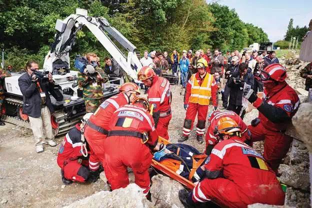
FIGURE 8.
Safe collaboration between human search and rescue workers and heavy robots (source: ICARUS consortium).
Simulated crisis response exercises are extremely useful, but the real operational validation of unmanned technology in search and rescue missions can only be done in a real‐life operation. Therefore, the ICARUS team did not hesitate when ICARUS partner B‐FAST was deployed to Bosnia in 2014 to help with flood relief operations after massive inundations to send along an expert in robotics and an unmanned aerial system (see also and Chapter 10). The mission was highly successful, providing assistance on the crisis sites not only for several international relief teams [B‐FAST, Technisches Hilfswerk (THW), …], but also for the Bosnian Mine Action Centre (BiHMAC). Figures 10 and 11 show how these relief teams were brought into contact with the new technological tool, provided by ICARUS, in collaboration with the TIRAMISU project. As we were during the mission tightly integrated with these end users and their procedures, this provided a deep insight into their requirements, procedures, indicating also the bottlenecks toward the integration of unmanned systems in the standard operating procedures of the search and rescue workers.
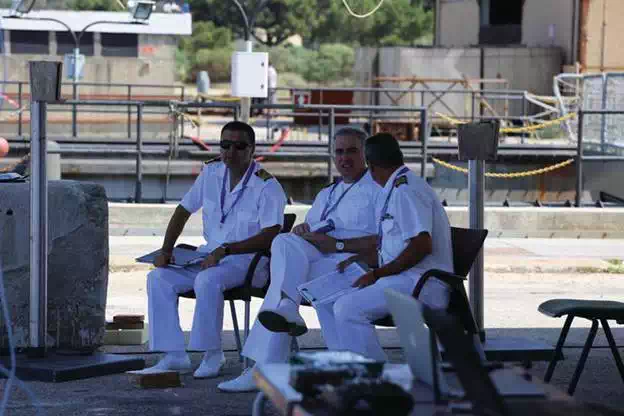
FIGURE 9.
Expert Navy officers evaluating the performance of the ICARUS marine tools (source: ICARUS consortium).
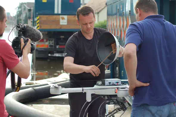
FIGURE 10.
Collaborator of the Bosnian Mine Action Centre being trained during operation on the use of unmanned aerial systems for mine risk mapping (source: ICARUS consortium).

FIGURE 11.
Operatives of the German relief team “Technisches Hilfswerk” (THW) being trained during operation on the use of unmanned aerial systems for damage assessment (source: ICARUS consortium).
Conclusions
Throughout the ICARUS project, end‐user engagement was one of the key focus points, as we realize that this was the main driver for acceptance of the technologies developed within the project and therefore also for the successful introduction of these tools on the terrain. A user‐centered design was adopted, as discussed in this chapter. This led to user requirements and the definition of user‐scripted operational validation scenarios for the ICARUS tools. Following the formalism of iterative user‐centered design, multiple intermediate validation trials were organized where the ICARUS systems were validated in more and more realistic environments. A lot of attention was paid not to validate only the pure technical capabilities of the systems, but also the very important nontechnical aspects like human‐robot collaboration, safe and legal operation, and rapid deployment.