Robot Protection in the Hazardous Environments
Response ability of chemical, biological, radiological, nuclear, and explosive (CBRNE) incidents is becoming more and more important. The hazards not only come from nature but also from humans, such as chemical weapons, collapsed coal mine, and the loss and leakage of radioactive materials. Once such disasters occur, it is crucial to figure out what has happened and how the incident develops. However, the condition and objects in the incident sites are always a great threat to humans, motivating unmanned systems to execute rescue tasks instead of people. Considering that hazardous environment has not only a bad influence to human fitness, but also can damage the unmanned systems. So, the protection technology of unmanned robots emerges into public vision.
In our research, there are several types of robots developed for dangerous environments: (1) Explosion-proof robot: the coal mine robot is a typical representative of explosion-proof robot. As the coal mine environment is filled with unstable areas and a variety of combustible gases, any small sparks can lead to a secondary explosion, so the explosion-proof design is an essential feature. (2) Biochemical sampling robot: the protection technology for such robot mainly comprises two aspects. One is to completely isolate the parts, which have a direct contact on dangerous sources. And the other is to carry out the waterproof design for decontamination process. (3) Radiation-resistant robot: radiation will cause irreversible damage to both electronic devices and rubber components of the robot, so designing a corresponding radiation-resistant layer is the foundation in the whole design process. (4) Fire-fighting robot: the remarkable characteristic of such robot is the strict temperature condition, which fluctuates between 80 and 200°C, so the additional requirement is to consider the protection methods against high temperature.
The remainder of the chapter is outspread in the following aspects: In Section 2, related work is stated and discussed. The working condition analysis and special protection design are presented from Section 3 to Section 6, corresponding to coal mine rescue robot, Biochemical sampling robot, radiation-resistant robot, and fire-fighting robot, respectively. Finally, Section 7 concludes the chapter and prospects for future work.
Related work
The CBRNE events may be released accidentally (e.g., industrial accidents or natural disasters) or intentionally (e.g., terrorist act), and rescue robots have been widely adopted in the rescue and intervention missions. Besides individual protection requirements for different tasks, the common point is related with decontamination process, which requests the waterproof performance of the robot.
Compared with general intervention systems, coal mine search-and-rescue robot systems need to be explosion-proof and waterproof, which is why few robot systems are employed in coal mine search-and-rescue tasks. Groundhog and Gemini-Scout robot were also utilized to detect underground coal mine situations. During the utilization procedure, the fact that current mine rescue robots had been reconstructed from generic mobile robots has been considered and discussed.
Biochemical sampling robot is always discussed as a sub-topic of the CBRNE intervention robot. A tele-operated wheeled vehicle with an underwater hydraulic manipulator was presented to cope with the CBRN intervention missions in Ref. According to Guzman et al. and Schneider and Wildermuth, the idea of modular platform was proposed where sensors could be exchanged and upgraded easily without touching the underlying base, which is similar to the decontaminable robot idea.
Until now, the world has already faced three serious nuclear accidents: the Three Mile Island accident in 1979, the Chernobyl reaction accident in 1986, and the Fukushima Daiichi accident in 2011, and teleoperated robots were used in all of these three accidents. As illustrated in Ref., several robots were used in the Three Mile Island not only for photographic/radiological inspection, but also for tasks such as concrete sampling and decontamination process. In contrast to the Three Mile Island accident, the robots applied in the Chernobyl nuclear plant nearly got nothing as the high dose rate, directing to the idea of interchangeable functional agents. When the Fukushima accident happened, the Quince robot performed prominently in the task and entered the reactor buildings seven times for dose rate measurement and water sampling. Other high-performance surveillance robots in recent years include HELIOS, developed by Prof. Hirose’s group, and ROBOT, developed by Bennett, P.C.
Ajala M proposed an indoor fire-fighting robot, which has the capability to climb stairs and negotiate several types of floor materials inside buildings. It can withstand very high temperature up to 700°C as long as 60 min using multiple thermal insulation technique. Kim J H et al. presented a multispectral vision system of robots used sensor fusion between stereo thermal infrared (IR) vision and frequency modulated-continuous wave (FMCW) radar to locate objects through zero visibility smoke in real time.
Coal mine rescue robot
Search and rescue robots are widely used in the coal mine disasters. As the coal mine environment is filled with various combustible gases, and any small sparks can lead to a secondary explosion, so the explosion-proof design is a necessary feature for the robot.
The mine rescue robot (MINBOT-II) developed in our laboratory is shown in Figure 1. The robot adopts the track-moving scheme with a pair of front and back swing arms, which can facilitate the efficient attitude adjustment, as well as obstacle crossing ability in the hostile environment. In addition, the swing arms adopted the modular design approach to reduce the weight of the integrated system, so they are easy to assemble and disassemble from the main track-body, forming different configurations as shown in Figure 1.

FIGURE 1.
Modular structure of MINBOT-II. (a) Robot without arms; (b) Robot with front and back arms; (c) Actual coal mine robot.
EXPLOSION-PROOF AND WATERPROOF DESIGN OF COAL MINE RESCUE ROBOT
Since the coal mine accident site is full of gas and coal dust, any spark may cause an explosion. Therefore, the apparatus working in coal mines must be designed based on explosion-proof technology. Since there is water in the coal mine, the rescue robot must be waterproof. A detailed description of the explosion-proof and waterproof design of the coal mine rescue robot will be discussed in this section.
The plane explosion-proof method, cylinder explosion-proof method, and gum-filling explosion-proof method are widely used in explosion-proof equipment. We applied these methods to design the mechanical system of the rescue robot, which is detailed in the following.
As discussed above, some electrical components, such as batteries, drivers, motors, and control systems, are nonintrinsically safe, thus they need to be packaged together in an explosion-proof box made of high-strength steel. For convenience of assembly and disassembly, the explosion-proof box is divided into three parts, and the interfaces between each part are designed using the plane explosion-proof technique, as shown in Figure 2(a). The cylinder explosion-proof technique is employed to make the motor power output shaft explosion-proof. Taking the back shaft, which has double layer outputs, for example [as shown in Figure 2(b)], the output shaft has an explosion-proof area with a 0.2 mm space and a length of 30 mm, as indicated by the red lines in Figure 2(b).
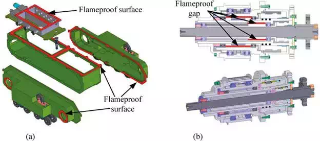
FIGURE 2.
Explosion-proof designs of the mechanical system. (a) Plane anti-explosion design; (b) cylinder anti-explosion design.
The explosion-proof box cannot be completely sealed due to the driving shaft, so the approach of filling inert gas is not feasible in the robot. However, we employed the gum-filling explosion-proof method in the battery box. As the gum is occupying the capacity in the battery box, the volume of flammable gases is sharply reduced. In addition to the principles listed above, two issues should be carefully considered during the design: (1) The explosion-proof box should be capable of isolating the flammable gas, able to withstand impacts, and prevent damage or deformation during the deflagration in the environment with high-density flammable gas. (2) When an explosion happens inside of the robot system, the energy must be consumed and released very fast through an unloading channel. As an example, in this section, in the cylinder explosion-proof design, we lengthened the flame propagation distance and reduced the spread gap [shown in Figure 2(b)], so the flame energy is consumed in the tunnel and cannot ignite the flammable gas before it spreads outside the box.
The explosion-proof and intrinsically safe design of the robot’s electrical system is illustrated in Figure 3. For intrinsically safe components that have to fulfill the intrinsically safe requirements, eliminating sparking and controlling temperatures are two main frequently used methods. The elimination of sparks is usually accomplished by limiting the stored energy (e.g., capacitance) in the circuit, while the internal short control method is commonly used to control the temperature. In addition, the intrinsically safe power supply is designed to isolate the power supply with explosion-proof devices, and the interactive signals between the intrinsically safe apparatus and explosion-proof apparatus are isolated in the physical chain. For the explosion-proof apparatus, the control system monitors high power consumption instruments and gives early warning of dangers.
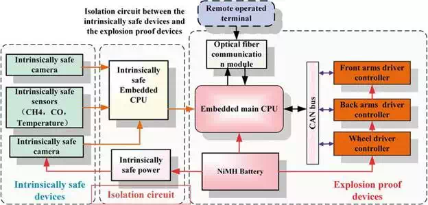
FIGURE 3.
Explosion-proof diagram of the electrical system.
To fulfill the water sealing requirements in coal mines, the protection grade of the robot has to be IP67. To realize this protection grade, the waterproof design is comprised of two methods, i.e., the whole body static sealing and the power output shaft dynamic sealing. For the static sealing method, the static waterproof (O-ring) is used at the transitions and connecting parts, while for movable components, such as the power output shaft, a dynamic sealing method is utilized, as shown in Figure 4. Springs are used between a static ring and a dynamic ring for compression, while the rubber sealing is used in the outer space. The rubber between the shells is the static sealing.

FIGURE 4.
Dynamic sealing design of power output.
COAL MINE ENVIRONMENT TESTS
To test whether the proposed robots (MINBOT-II) fulfill the requirements to work in a coal mine environment, several test experiments were carried out by the laboratory of the Chinese Administration of Work Safety.
A blasting test method was carried out to test the explosion-proof performance of the robot. In the test, the robot was filled with high-concentration CH4 after being assembled. It was then put into a room filled with flammable gas. Lighting the CH4 inside the shell, any fire leak and any deformation of the shell are impermissible, because they will make the flammable gas outside the shell (in the room) ignite.
The result of the explosion-proof test is shown in Figure 5(a). The left frame shows the electrical connectors between the isolation box and the explosion-proof box after an explosion. The connectors, marked with a red circle, are undamaged. The right frame shows the flameproof surface of the explosion-proof box, marked with a red box. The surface is clean and undamaged after an explosion, and the test results show that the shell meets the explosion-proof requirements. The test results show that the shell meets the explosion-proof requirements.

FIGURE 5.
The result of (a) explosion-proof and (b) waterproof test.
To validate the waterproof design of the robot, a static sealing waterproof test and a dynamic sealing waterproof test were performed. In the static sealing waterproof test, the shell was immersed in water, as shown in Figure 5(b), the output shafts ran properly and leaking did not occur after 4 h. In the dynamic waterproof test, the shell was also immersed in water with all power output shafts running at different speeds, and leaking did not occur after 4 h.
Biochemical sampling robot
Biological and chemical hazards vary dramatically, such as the biochemical weapons, virus infections, leakage of toxic chemicals, and industrial discharges. As robot worked in this, environments will be polluted, and decontamination is a most popular method used to clean robot. Therefore, waterproof and special sampling tools should be designed.
The biochemical sampling robot developed in our laboratory is shown in Figure 6. Several functional equipment are integrated on the tracked mobile platform: a 6-DOF manipulator with a 1-DOF parallel gripper is mounted on the front of the robot; a set of sampling instruments is specifically designed and fixed in the middle of the robot and the end of the robot is provided with the communication system and pan-tilt vision system. In the following section, the protection design is presented in two aspects, namely decontamination design and sampling instrument design.

FIGURE 6.
The biochemical sampling robot and tests.
PROTECTION DESIGN OF BIOCHEMICAL SAMPLING ROBOT
When robot performs the sampling tasks in the biochemical environment, the hazardous material may contaminate the sampling robot, resulting into a new moving contaminated source. So, the decontamination process is an essential process when the robot completes the sampling task and traverse back to the safe domain. However, the decontamination procedure may cause damage to the sensitive parts of the robot. Therefore, two kinds of protection methods are commonly adopted: one is the shielding protection, namely placing a certain type of shielding material clothes, while painting protective materials is another method. Additionally, waterproof is also indispensable.
Apart from the shielding protection method of which the shielding clothes differ in specific hazardous situations, the painting method and waterproof method are carried out in the design process. (1) Considering the good permeability of several chemical reagents, Fluoride painting is employed to prevent the chemical reaction between the metal shell and the reagents. Moreover, side-protecting plates are added on the side of the track vehicle and swing arms, to prevent the hazardous materials (especially liquid) from sputtering into the track system, reducing the working intensity of decontamination task. (2) The waterproof design is similar to the coal mine robot illustrated above of which the protection grade against dust and water is IP67. The static waterproof method and dynamic sealing method are utilized for the robot (see part 3.1 for detailed information). Besides above protection approaches, the electrical interface which is exposed to the hazardous environment should adopt the aviation plug to ensure the connection reliability and waterproof performance.
According to Guzman et al., the identification of biochemical objects on a portable sensor unit is still not possible nowadays. Hence, samples in the hazardous domain should be acquired and taken back by sampling robot for further analysis in external laboratory. As the core devices of the biochemical sampling robot, the sampling tools and sampling container should be designed in the following aspects: (1) Sampling instruments should be conceived to meet the requirements of sampling different materials. (2) The position tolerance ability is considered as the positioning accuracy of the arm is affected by the vibration of the vehicle motion. (3) The sealing feature of sampling instruments is also required, due to the infectious and corrosive features of biochemical materials.
Through analysis and generalization of biochemical sample’s properties, several typical sampling objectives can be summarized as follows: liquid on the surface, liquid in the deep hole, soil, powder, and little pieces of solid. According to the properties of different sampling objects, the corresponding instruments are designed with the modular method, as listed in Table 1. And the sampling instrument comprises sampling tool, sampling container, and position tolerance base, as shown in Figures 7 and 8.


FIGURE 7.
Five crucial kinds of sampling tools: (a) dry cotton ball tool, (b) bucket tool, (c) shovel tool, (d) wet cotton ball tool, (e) tweezers tool, (f) the components of sampling tools.
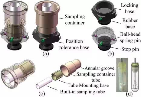
FIGURE 8.
The sampling container and mounting base: (a) sampling container and mounting base, (b) position tolerance base, (c) the components of the sampling container, (d) built-in sealed sampling tube.
To meet the position tolerance between sampling instruments and end-effectors, the mounting base can be divided into two layers: the aluminate alloy locking layer and the rubber tolerance layer. The former is attached to the sampling container with spring pin and stop pin, while the latter is fixed on the track vehicle and ensue the ability of position tolerance.
The sealing feature is also considered in the design. As illustrated in Figures 7(f) and 8(c), a built-in plastic tube is inserted into the sampling container, while a sealing plug is integrated into the sampling tool. When the sampling robot traverse back to the safe domain, the sealed samples can be obtained directly through the detach knob mounted on the top of sampling tool, without worrying about the spread or damage of the hazardous samples, as shown in Figure 8(d).
The rapidity ability of sampling task is considered in the mechanical design. The mechanical modification mainly focuses on the interface between end-effector and sampling tools, as well as the interface between sampling tool and sampling container. As shown in Figure 9(a), a rectangular groove is added on the handle of the sampling tool, and a spiral structure is adopted for the interface between sampling tools and sampling containers. The former design feature ensures rapidity and reliability of the end-effector grasping process, while the later one realizes the position tolerance and the sealing performance between sampling tool and sampling container.
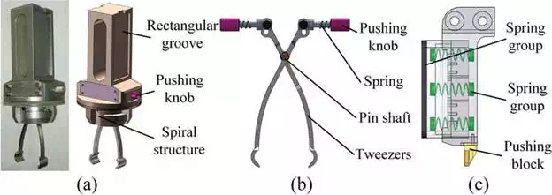
FIGURE 9.
Quick change interface of the sampling tools. (a) Design features of tweezers tool, (b) clamping principle of tweezers tool, (c) quick change interface for th gripper.
BIOCHEMICAL SAMPLING TEST
As waterproof design of biochemical sampling robot is similar to coal mine robot, so the test is not illustrated here. The test for sampling process was conducted and the appliances include a set of sampling instruments, a sampling robot with a 6-DOF manipulator and a parallel gripper, a teleoperation box, and five kinds of samples, as shown in Figure 6. The autonomous step of pick and place sampling tools makes the sampling task faster and easier, while the sealing character of the built-in sampling tube works successfully.
Radiation-resistant robot
With the deepening utility of the nuclear energy, nuclear power is becoming a potential alternative energy solution, and nuclear power is also widely used in industry, health care, education, and other fields.
We designed a robot for handling out-of-control radioactive sources as shown in Figure 10. The robot employed a wheel-track hybrid mobile system with a front swing arm, equipped with a 7-DOF manipulator for redundant obstacle avoidance operations.

FIGURE 10.
The radiation-resistant robot.
CONSIDERATIONS FOR DESIGN PROCESS OF RADIATION-RESISTANT ROBOT
In the above scenarios, radiation would cause irreversible damage to both electronic devices and rubber components of the robot, leading to the failure of radioactive emergency task, so radiation-resistant layer is the foundation and a dispensable step in the overall design process. However, the resistant materials are often very heavy; the optimization between radiation-resistant ability and mobility should be considered and weighted up. The development of radioactive protection methods and factors are synthesized, and the mission requirements of radiation-resistant robot are indicated in the following.
PROTECTION DESIGN OF RADIATION-RESISTANT ROBOT
The design process of the radiation protection is organized by the following sections. First, the mechanism of radiation is analysed. And then based on the common used radiation sources and shielding materials, we analyze and calculate the capacities of protection of different materials and determine the required location and thickness of shielding protection according to the sensitivity of different devices to radiation. Finally, by weighing the robot’s mobile capability and radiation-resistant performance, the final shielding material and its corresponding thickness are determined, and the design of the shielding layer is completed.
Nuclear radiation mainly refers to the energy emission process of radioactive materials in the form of waves or particles through space. The generated electromagnetic waves mainly comprise α, β, or γ rays, consisting of helium nuclei, electrons or positrons, and photons, respectively. As these rays can be understood as particles emitting from the radioactive materials, their penetration ability is different, as illustrated in Figure 11.
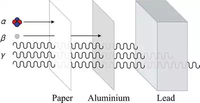
FIGURE 11.
The penetration ability of α, β, and γ rays.
The α particles could be stopped by a sheet of paper, while β particles are blocked by an aluminate plate. These two radiation should be omitted in design consideration for their weak penetration ability, but γ radiation should pay more attention in protection design. The γ radiation has strong penetration ability that thick lead plate can just damp its intension, and it is the main cause of the devices damage.
As γ radiation is a kind of electromagnetic wave, the radiation intensity is inversely proportional to the square of the distance. They are given in the following way
![]()
where I0 is the intensity of the radioactive source, I′0I0' is the intensity at the measurement site, and L is the distance to radioactive source.
According to the Beer-Lambert law, the attenuation of γ radiation across solid materials is as follows:
![]()
where I0 is the radiation intensity before passing through an object with the unit of Gy, I is the radiation intensity after passing through the object with the unit of Gy, μ is the linear attenuation coefficient with the unit of cm-1, μm is the mass attenuation coefficient with the unit of g/cm3, and t is the thickness of shielding material with the unit of cm.
In the material attenuation formula above, the linear attenuation coefficient varies depending on the photon energy of the radiation source and the radiation protection material. Therefore, to determine the commonly used shielding material, linear attenuation coefficient is an indispensable part of the design process and will be presented in detail as follows.
According to Changsong, the mass attenuation coefficients, μm, of the same material are different at different photon energy levels. Table 2 shows the mass attenuation coefficients for several common shielding materials at different gamma-ray energy levels.
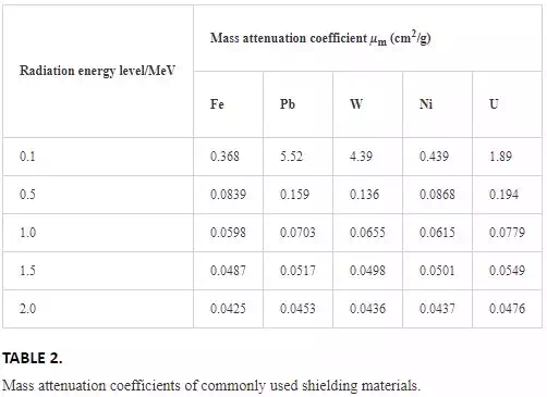
As for the mass attenuation coefficients of the alloys or mixtures, they can be calculated according to the percentage of each element. Take tungsten-nickel-ferrum alloy (95W3.5Ni1.5Fe) as an example, the mass attenuation coefficient can be calculated through the following formula:
It can be found that the commonly used radioactive sources are Co60, Cs137, Ir192, I131,etc. The specific data are shown in Table 3.
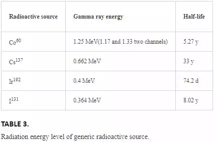
According to Table 3, the average energy of Co60 gamma ray is the highest among the commonly used radioisotope, which is up to 1.25 MeV. Considering the protective performance of the shielding material, it will weaken with the increase of γ-ray radiation energy. Therefore, the protection design of the robot is selected under the most demanding conditions, which is 1.25 MeV.
According to Taoyi [15], the commonly used shielding materials include tungsten, plumbum, uranium, and tungsten-nickel alloy.
By interpolating the mass attenuation coefficients at 1 and 1.5 MeV in Table 3 and checking the corresponding density, the attenuation coefficient of each material at 1.25 MeV is obtained, as shown in Table 3.
The radiation shielding design of robot is divided into two steps: first to analyze and determine the radiation sensitive electronic components and their corresponding positions. Then through comparison and calculation, one can finally determine the material and the corresponding thickness.
As discussed in Refs., the radiation-sensitive components in robot mainly include electronic components located in the body and various sensors exposed to the environment. For the electronic components installed inside the robot, taking into account the overall protection of mobile platform and manipulator will greatly increase the weight of the robot, thus affecting its motion flexibility. So the radiation-resistant protection for internal components are achieved by the method of centralized method, namely the components are put together in a shielding box, while the method of separate protection is adopted for some scattered components. For the encoder, the controller and the drive, a shielding layer should be installed on the side of the vehicle body; for the external visual sensor, the shielding material is used for the overall coating, while the front of the CCD sensor is made of lead glass. Meanwhile, the shielding coating is applied to the inner wall of the vehicle body and the manipulator. The protection for vehicle body and the manipulator are shown in Figure 12.
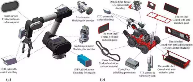
FIGURE 12.
The radioactive shielding protection of the robot. (a) Radioactive shielding protection of maniulator, (b) radioactive shielding protection of track vehicle.
After determining the protection position of each electrical component, the appropriate material and its thickness can be calculated and selected. According to the radiation lifetime test in Ref., the electronic device can be divided into CCD sensor, motor and drive, laser ranging sensor, and other electronic devices. The cumulative dose of radiation that can be sustained by each kind of device is shown in Table 4.

Based on the attenuation law of gamma radiation through solid material, the cumulative radiation dose rate of different materials in different thicknesses in external environment can be obtained. Taking the normal working time of 3 h as the standard, the critical radiation dose rates of radiation-resistant materials in different thicknesses are calculated, just take the condition of 3 mm thickness as an example, illustrated in Table 5.
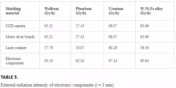
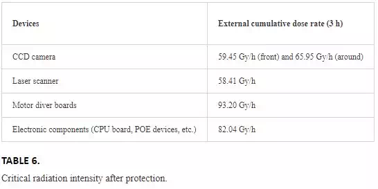
Finally, we need to balance the vehicle’s weight and mobility, as well as the material’s processing performance and radiation protection capability, and then the radiation protection material and its corresponding position can be determined. Meanwhile, the distance factor that the cumulative radiation dose of the vehicle is less than that of the manipulator should also be taken into account. After comprehensive consideration, the lead and high-lead glass are chosen as shielding materials, where the thicknesses for manipulator, vehicle, CCD front glass, visual sensor and laser ranging sensor are 10, 3, 8, 5, and 5 mm, respectively. The critical ambient radiation intensity for each part to maintain normal operation for 3 h is shown in Table 6. Taking the attenuation of radioactive sources in the air into account, it is appropriate that the radiation resistance of vehicle and laser radar is weaker than that of motors.
After a certain amount of radiation dose, the rubber will be molecular bond breaking, degradation, or re-crosslinking. So, some of the robot components (such as tires, crawlers, and cables, etc.) need to be carefully considered during design. It has been proved in Ref. that Ethylene Propylene Diene Monomer (EPDM) has good resistance to aging and radiation. By adding a radiation-resistant agent (Bi2O3), its anti-fatigue strength and radiation resistance will be further strengthened. Such a material will be used for robot’s rubber components.
As for the cable in the wired communication system, the semiflexible/semirigid coaxial cable is chosen with the radiation resistance more than 106 Gy, and can be used for a long time working at the temperature range of −100 to +150°C. The cable can be used for signal transmission, comprising inner conductor, insulating layer, outer conductor, and sheath layer.
IRRADIATION TEST FOR ELECTRONIC COMPONENTS
The following will describe the specific process of irradiation experiment according to Nagatani. The electronic components for the irradiation experiment include a CPU board, a motor with an encoder, a motor driver board, a wave power transfer device, a visual CCD sensor, and a laser radar. The test is intended to use three linear Co60 as radiation sources. For safety, we place the radiation source in an underground cooling pool. When the experiment begins, raise the radiation source to the center of the shield test area to radiate the surrounding objects. The cumulative irradiation of the target can be adjusted by the distance to the radiation source. Theoretically, the radiation intensity decreases with the square of the distance. In the Japanese irradiation experiment, the radiation intensity of the γ source at 0.66 and 0.45 m from the radiation source are 20 and 40 Gy/h. More details will be discussed below, and the experimental device and space layout are shown in Figure 13.
1. Restarting tests of computer motherboard: As shown in Figure 13, the computer motherboard is located at the distance of 0.6 mm from the radiation source. Considering the motherboard can still work after the flash card is destroyed (the flash card is mainly used for computer system startup function), we need to restart the computer every 30 min to confirm whether the flash card is failure.
2. Tests of sensors: Sensors are placed at the distance of 0.45 m from the radiation source. The CCD, laser radar, and photoelectric switch are connected to the monitoring computer via the LAN. The measurement results of sensors are obtained by an external monitoring computer, and the times of abnormal and complete failure of the image are recorded.
3. Tests of motor drivers: The motor driver is placed at the distance of 0.45 m from the radiation source, and connected to the monitoring computer via Controller Area Network (CAN) bus by continuing to send virtual commands to detect whether it fails. The motor can be considered to be placed outside the irradiation room to the effectiveness of the driver.

FIGURE 13.
The test devices and spatial layout of irradiation tests. (a) Device configuration for the irradiation test, (b) layout of devices and experimental facility.
By recording the experimental results, we can find that the radiation resistance data are similar to the results of Ref. [10] and also prove the correctness of the previous subsection theory.
Fire-fighting robot
The conflagration accident is another typical hazardous condition, which is dangerous and hostile to rescuers. This dangerous environment is filled with thick smoke and high temperature, as well as flames everywhere. In consideration of these challenges, two approaches are utilized to cope with the hostile situation: (1) waterproof and dustproof design is dispensable as the debris and water in the fire site and (2) high temperature resistance design is also necessary for the robot inside components protection.
The fire rescue robot is shown in Figure 14, comprising main body, high-pressure sprinkler and control box. The track system includes flame retardant rubber externally and metal skeleton internally, ensuing the walking ability and stability even in the worst condition that the rubber melts for high temperature. Additionally, the autonomous cooling sprayer is also integrated to ensure the normal work in the high temperature.

FIGURE 14.
The fire-fighting robot and tests.
TEMPERATURE PROTECTION AND WATERPROOF DESIGN OF FIRE-FIGHTING ROBOT
As the temperature in the field of flame can reach up to 700°C, and nearly everything will be melt. Hence, the high temperature resistant ability should be discussed and conceived. Moreover, the cool water is inevitably sprinkled on the robot, and the waterproof technology is also needed.
The temperature resistance design is implemented through the autonomous cooling sprayer, which can spray cooling water on the whole body of the fire-fighting robot. This approach has two advantages: (1) the high-pressure water cannon is the essential tool for fire controlling; the autonomous cooling system is just an additional application of the drainage system and (2) other approaches for temperature resistance, such as the thermal insulation, will increase the design difficulty and the overall weight of the robot, reducing the traffic-ability and crossing ability. So the autonomous cooling sprayer may be the best selection.
In order to satisfy the requirements of waterproof and dustproof sealing performance, protection grade of the robot must reach IP67. The mechanical design comprises of two methods: the static sealing method and dynamic sealing method, which is similar to the waterproof implementation of coal mine robot (as illustrated in part 3.1.3). The specific implementation details will be omitted.
FIRE-FIGHTING ROBOT ENVIRONMENT TESTS
In order to test whether the fire-fighting robot can meet the requirements in the fire environment, Tangshan fire-fighting robot was utilized in the Imperial Palace Museum (shown in Figure 14) and other places for fire drills to testifying the validation of this robot and the protection technology.
The first fire drill was held in the oil storage tank domain, assuming the fire broke out suddenly and the fire had been out of control. As the fire had been out of control, temperature nearby was rather high which was possible for rescuers to get close. Three fire-fighting robots rushed into the core field of fire under the operators’ commands, and the fire was under control quickly, as shown in Figure 15.

FIGURE 15.
The high temperature protection tests of the fire-fighting robot.
Conclusions and future work
In this chapter, protection technologies for four kinds of rescue track robots are discussed and presented to assist the CBRNE emergency. The specific protection technology for the four track robots is listed as follows: (1) The coal mine robot is modified by mechanical shielding, components reposition, and electronic protection, getting a good performance for explosion-proof and waterproof. (2) Biochemical sampling robot realizes its protection technology through a 6-DOF manipulator and several sampling instruments, as well as the waterproof design against decontamination. (3) Radiation-resistant robot completes the radiation shielding design and rubber components selection, satisfying the requirements of working well in the radioactive environment. (4) The fire-fighting robot adopts the high temperature resistant design and waterproof technology to ensure the robot can work in high temperature environment.
The future works may focus on the followings: as the diversity and distinction of hazardous conditions, we need to dig more deeply into requirements and protection methods of different hazardous environment. In addition, the tradeoff between the protection level and other performance of the robot should be optimized and considered, such as balancing the traffic-ability and radiation-resistant ability in the radiation-resistant design process or the types of sampling tools and dimension of the track-vehicle.