UAV for Landmine Detection Using SDR-Based GPR Technology
Ground-penetrating radar (GPR) is currently a well-accepted geophysical technique which has been successfully deployed with the aim of addressing important sensing problems that requires detection, imaging and identification of dielectric material discontinuities in the subsurface through the use of radio waves, providing a non-invasive method to probe the ground. With the existence of different subsurface scenarios with diverse lossy dielectric materials combined with the broad radio frequency, spectrum leads to a wide range of GPR applications. Among these applications, the potential of GPR systems can be extended to landmine detection, considering its intrinsic capacity of detecting electric conductor objects buried into the subsurface.
Nowadays, there are several types of GPR commercially offered. However, within the wide range, two kinds of GPR systems can be identified upon the manner in which the data is acquired, either in time domain or in frequency domain. Most of commercial GPR systems in use today employ time domain methods and fixed RF electronics to implement impulse-based radar techniques where a time domain pulse is transmitted and the reflected energy is analysed as a function of time. The resulting waveform indicates the amplitude of the backscattered energy from the subsurface structures versus time where range information from objects within the subsurface is based on the time-of-flight principle. In terms of size and weight, the main drawbacks of commercial impulse GPR systems are their high price, oversize, overweight and the low adaptability of the system according to the needs of detecting different sizes, types of landmine building materials, and different dielectric characteristics of the terrain due to a fixed-hardware implementation. The limitations of oversize and overweight restrict the fact that the GPR could be installed on-board an unmanned aerial vehicle (UAV) system.
The topics presented in this chapter explore the potential of the software-defined radio (SDR) technology to provide flexible, cost-effective and low-weight radar prototypes for GPR application in the detection of metallic buried landmines. Landmine detection and clearance are one of the primary humanitarian necessities mostly in developing countries with internal war conflicts, for instance, Colombia, which is currently one of the most mine-affected countries in the world. Since 1990, the Colombian government has registered 10,751 victims of explosive landmines: 39% corresponding to civilians and 61% to the military. Although the internal conflict in Colombia is coming to an end, there still are many regions in the country with over 10,000 potentially hazardous areas that require urgent mine clearance, according to recent Colombian government statistics. Besides, most of the landmines in those countries are improvised explosive devices (IEDs) which impose the requirement of the prior knowledge of the target features in order to discriminate between the target and safe objects. IED detection is a challenge due to similarity between IEDs and common objects such as PVC pipes, cans and other objects that are used in the explosive device fabrication. Therefore, the use of SDR in GPR systems can significantly contribute to the identification of IEDs due to its intrinsic capacity of software adaptability.
This book chapter presents an approach for detecting buried landmines by using an autonomous drone equipped with a custom-designed SDR-based GPR system. Figure 1 details the proposed robotic setup, mainly composed by (i) the GPR system (USRP B210 board, RX and TX antennas and SMA connectors) and (ii) the drone’s on-board hardware (high-level and low-level processors, ZigBee communication module, IMU, GPS and LIDAR sensors). One key aspect to achieve a reliable GPR’s operation relies on the precise navigation of the drone, which must flight steady in spite of wind disturbances. In addition, the drone must flight at a very low altitude to allow the GPR’s emitted signals to properly radiate the subsurface (about 50 cm over the ground). Consequently, the navigation controller must take into account the ground effect.
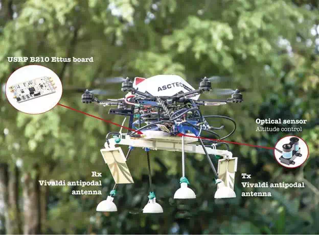
FIGURE 1.
Asc Tec Firefly drone equipped with the custom-designed ground-penetrating radar using SDR methodology.
Comprehensive literature review
WHAT ARE SDR AND GPR TECHNOLOGIES?
The origin of the software-defined radio technology is related with the military field, specifically to the Defence Department of the United States with the Integrated Communications, Navigation, and Identification and Avionics (ICNIA) system in the 1970s. Later on in the 1990s, the SpeakEasy project started with the purpose of developing a software programmable radio systems operating in the band between 2 MHz and 2 GHz. This project can be considered as the base of the SDR technology.
In the mid-1990s, Joseph Mitola creates the SDR forum given a detailed description of the technology defining SDR from the engineering design, topological structure and computational structure perspectives. In summary, SDR can be understood as a reconfigurable radio system which substitutes the hardware components such as mixers, filters and modulators into software components by using computing embedded systems. The basic SDR systems are composed by an embedded system with a field programmable gate array (FPGA) interface with a digital-to-analog and analog-to-digital conversion (DAC and ADC, respectively) both adapted to a radio frequency trans-receiver system.
GPR, being the acronym of ground-penetrating radar, is a system able to irradiate electromagnetic waves below the earth surface strata and can detect buried objects or differentiate between soil layers by using the principle of reflectometry by dielectric discontinuities of the media. The interaction between electromagnetic waves and the objects located within the radar illuminated area produces the so-called backscattered wave, an echo signal that propagates back towards the surface which can be detected by the GPR receiving antenna for post-processing to obtain underground maps or information of subsurface terrain including the buried objects. The use of radio waves to image the earth was contemplated for decades before some primary results were obtained in the 1950s. From that time, there was a gradual transition of the concepts to sounding soils and rocks in the 1960s and has continued ever since. Nowadays, applications have flourished, leading to a wide research area. A brief historical review is presented in. Some of the current GPR applications are (i) description and characterisation of geological faults, soil stratification, field exploration and mineral resources; (ii) characterisation of materials and structures made of wood, concrete and asphalt; and (iii) detection and identification of buried objects (pipes, cables, barrels, archaeological objects, landmine detection).
Currently, the landmine detection and improvised explosive devices (IEDs) using GPR are the subject of research. The GPR allows detecting both metallic and non-metallic targets in a non-invasive fashion. Unlike metal detectors, GPR technology increases the detection depth range and reduces the false alarm rate. Several GPR technologies and techniques have been addressed in literature oriented to perform a more efficient demining process.
There are several types of GPR; the main difference is the way in which data are acquired, either in time domain or in frequency domain. As an instance, impulse-based radar systems operate in the time domain, while continuous-wave (CW) radar operates in the frequency domain. GPR system can be based on other technologies such as stepped-frequency radar, ultrawide band (UWB), synthetic aperture radar (SAR) and arbitrary wave.
SDR FOR GPR SYSTEMS
Since the introduction of the SDR concept, one of the most promising applications that have been taken from is radar. The advantages presented by the SDR technology suits perfectly with the oversize and overweight drawbacks of a traditional radar system. In this manner the term software-defined radarhas showed up in the picture as a novel paradigm which gives a more versatile solution by implementing the fundamental radar operations such as signal generation, filtering and up-and-down conversion via software. Despite of the synchronisation issues given by the digital nature that the SDR technology can have, undoubtedly the software domain provides advantages such as (i) the possibility to create multipurpose radar, (ii) the possibility to reuse the same hardware, (ii) an easier implementation of advanced signal processing algorithms, and (iii) a faster development and a cost-effective solution. In the last decade, many scientists and researchers are focusing their attention in SDRadar systems and their applications in different test beds considering the Universal Software Radio Peripheral (USRP) as the hardware base and GNU Radio, an open-source software-defined project, as a software tool to implement very sophisticated, cost-effective radar applications.
In the follows, some contributions of SDRadar system are presented. Debatty in presents a compressive state-of-the-art review of the SDRadar technology by approaching from the design concept and global assessment perspectives. In particular, the author mentioned the wide varieties of airborne SDRadar including the one for a UAV to sense and avoid collisions with other flying objects. The work in presents the potentialities of the USRP-based software-defined radars presenting the design and implementation of an SDRadar system for target tracking and the experimental characterisation of the radar on a USRP board obtaining improved radar resolution results with respect to previous works. Other works like the one of Aloi et al. approach in a more detailed fashion presenting the synchronisation issues and practical implementation of a radar system by using Simulink toolbox interface instead of GNU Radio in a USRP device. Recent contributions have shown novel software radar techniques; Costanzo et al. in proposed SDRadar based on orthogonal frequency division multiplexing (OFDM) for soil discontinuity detection taking advantage of the well-known benefits of the multicarrier radar signalling technique employed in various application fields, such as remote sensing of wheatear forecasting, detection of buried objects and interpretation of urban scenes. In the other work presented by the same authors, a high-resolution L-band SDRadar is presented for target detection using the USRP NI2920 enhancing the radar bandwidth and range resolution by exploiting the Gigabit Ethernet interface of the SDR system.
UAV FOR DEMINING APPLICATIONS
Unlike terrestrial landmine detection mechanisms, the use of unmanned aerial vehicles (UAVs) is clearly suited for covering a minefield without the risk of triggering landmines during the mission. However, the weight and size of the sensing systems used for demining are unlikely to be placed on UAVs due to their poor payload capacity. In, the authors proposed the fabrication of a small multi-frequency ground-penetrating radar (GPR) on-board a UAV quadrotor able to lift up to 1.1 Kg of payload. The GPR was designed to be a multiband reconfigurable antenna able to switch among a range of radiating frequencies within 0.5–5 GHz with a bandwidth of 350 MHz to 5 GHz. Despite the designed GPR was able to characterise buried landmines with different shapes and depths, the results were conducted in lab experiments with the GPR off-board the UAV, not considering the factors involved in the integration on-board.
So far, biological sensors used by animals (e.g. dogs and rats) provide the highest accuracy in terms of landmine detection. However, to avoid the use of trained animals for demining purposes, authors in have proposed a blimp-based chemosensing UAV with a bio-inspired detection architecture composed by a six-grid array films responding to a wide range of volatile organic compounds. The system creates a map of the terrain with the information provided by the chemosensor. The advantage of this chemosensor technology relies on its small size; however, the sensitivity can go up to few particles per million (ppm), which might not be enough for detecting explosive particles such as Trinitrotoluene (TNT) or Dinitrotoluene (DNT).
In [25], an airborne LIDAR system integrated with laser scanner, GPS and inertial-measurement unit (IMU) is proposed. The system is able to detect TNT and DNT using sensitive biosensors based on the soil bacterium Pseudomonas putida. By reflecting a green laser light at a wavelength of 532 nm over the explosives, they emit a red fluorescent light. In this regard, multispectral cameras can be used for capturing the traces of fluorescent light. So far, the lightest multispectral cameras commercially available are able to capture visible light wavelengths longer than 520 nm and near-infrared wavelengths up to 920 nm. They might be an interesting choose for landmine detection.
SDR-based GPR design
As detailed in Figure 1, the open-hardware platform USRP for developing custom SDR configurations has been used to implement the GPR device. Here, GNU Radio is used, a free and open-source Python programming graphical user interface for software-defined radios to facilitate SDR development. By using the SDR functions contained within the GNU Radio framework, the most fundamental operations of the GPR, such as signal generation, filtering and up/down conversion, are easily implemented via software (unlike the traditional fixed-hardware implementations). Despite the development of SDR has gained a great impact, its full potential has not been fully exploited for radar-based applications applied to landmine detection, concretely, by integrating a GPR into a drone.
The GPR hardware system is composed by two main blocks, the transmitter (TX) and receiver (RX), as shown in Figure 2(a). The Tx module generates the pulse, which is then shaped by a root-raised cosine filter in order to reduce the frequency bandwidth of the signal due to the restrictions of the platform itself. The pulse modulates a carrier that is finally transmitted to the USRP platform to being radiated by the TX antenna. The radiated modulated pulse travels along the path air-soil, and in case of detection, there is a reflected wave, which is sensed by the RX antenna. The RX system down-sampled the signal. The amplitude and delay of the received signal are then post-processed using MATLAB aimed at generating the heat map shown in Figure 2(b). The forthcoming subsections detail on GPR modelling and design.

FIGURE 2.
(a) High-level USRP architecture for the GPR implementation; (b) (experimental) post-processed heat map indicating landmines buried in the covered terrain.
MODELLING
In order to design and develop the functionalities described, the design considerations described in Figure 3 have been established. In the first place, the technical specifications of the GPR are defined by taking into account the operational requirements, such as signal frequency operation and bandwidth, propagation speed in different media, noise, etc. Also, it is considered how the aforementioned variables might be affected by the target and material properties. This analysis enables to define and design criteria for developing the antennas, the required hardware and the signal processing algorithms. Finally, GPR storage and visualisation process refer the way how information is stored and presented to the final user.
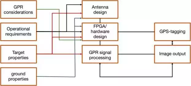
FIGURE 3.
Consideration for GPR designing.
A simple geometrical scheme (shown in Figure 4) is proposed for setting the inclination angle for both antennas based on analysing reflection and refraction properties that depend on soil materials and target location. This model uses the following geometrical parameters: S is the distance between both antennas, θ1 is the inclination angle, θ2 is the signal refraction angle (due to the change of media from air to ground), r1 is the directional distance between the antenna and the terrain, r2 is the directional distance to the target (below ground) and a is the antenna altitude with respect to the terrain. By considering the Snell law and applying some trigonometrical properties, the geometrical model is described by Eq. 1:
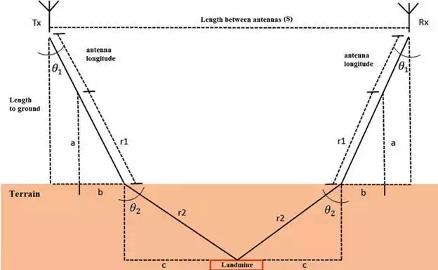
FIGURE 4.
GPR geometrical model for signal transmission and reception.

where the relative air permittivity such as ε1 = 1, the antenna length of 0.28 m and the distance to the terrain 0.4 m are considered. The terrain permittivity (ε2) can vary drastically, especially in the presence of water particles, and is usually a complex, frequency-dependent quantity with real and imaginary components. For GPR models, it is convenient to simplify the permittivity value to its constant, low-frequency real component with the loss term ignored. This is convenient for the approximate calculation of radar wave velocities, wavelengths and medium impedance; however, it is still too general for a detailed analysis. Relative permittivity of different subsurface materials was taken from [43] and is listed in Table 1.
Typical values of relative permittivity and static conductivity for common subsurface materials at 100 MHz [43].
The dielectric material considered for the terrain in the model was a soil (sandy) material considering the limit between dry and low humidity with relative permittivity (ε2) between 4 and 10. Table 2 shows the geometrical model data obtained from Eq. (1) for three different incident impinging wave angles.

Power losses are a common phenomenon that must be involved in the development of a GPR system because as described in Figure 5 the signal faces different changes of medium not only from the air to the subsoil but also within the soil itself. Other signal phenomena should be considered as well like multi-trajectories by reflections of the same signal on the different media surrounding the measurement area. It is also necessary to take into account the distance and alignment between the transmitting and receiving antennas and the backscattered signals.
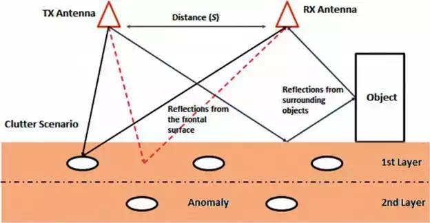
FIGURE 5.
Backscattered signal phenomenon in a GPR scenario.
According to, the range of the GPR is primarily governed by the total path loss, and the three mainly contributions are the material loss, the spreading loss and the target reflection loss. It should be noted that the considered path loss model, for the sake of simplicity, contains many simplifying assumptions, mainly relating to the spreading loss. In conventional free-space radar, the target is in the far-field zone of the radiating antenna, and the spreading loss is proportional to the inverse of the fourth power of distance provided that the target is a point source. In many situations relating with ground-penetrating radar, the target is in the near-field zone making the relationship no longer valid. However, for this model, R−4 spreading factor is assumed. To model this issue, there were eight factors considered that are related to signal power loss. Then, the overall loss LT can be modelled as
![]()
where Le is the loss due to the antenna’s efficiency, and considering both transmitting and receiving antennas, the total efficiency loss in the path loss model is Le = −4 dB. Antenna’s efficiency losses were estimated for a loaded dipole antenna; however, for directive antennas, the efficiency is higher and lower losses can be expected. Lm is the antenna mismatch loss, and due to the good match of the antenna shown in lab measurements, it was considered in the order of Lm = 1 dB. Lvd is the loss due to antenna’s vibrations caused by the drone, Lt1 is the loss due to the change of the propagation medium (from air to ground), Lt2 is the loss due to the propagation from ground to air, Ls is the antenna spreading loss, La is the loss due to signal attenuation and Lsc is the target scattering loss. Lt1 and Lt2can be calculated considering the power transmission loss coefficient defined as τ = 1 – |Γ|2, where Γ is the reflection coefficient which can be computed knowing the air and soil impedance Za and Zm, respectively. Assuming a normal impinging wave, Γ is defined as
![]()
By replacing Eq. (3) into the power transmission loss coefficient and computing the power loss in dB, the expression for the transmission coupling loss can be defined as
![]()
Being Za = 377 Ω and Zm obtained by the expression in (7), giving that the subsurface material is mostly soil (sandy) and considering an average dry-wet condition, so the relative permittivity for the terrain was assumed as ε2 = 8 and the loss tangent was computed by the known expression tan(δ) = σ/(ωϵ) considering a conductivity given by σ = 10 mS/m:
![]()
Obtaining a terrain impedance Zm = 130 + j15 Ω, by considering only the real component of the impedance, the air-ground transmission coupling loss is Lt1≈2.5dBLt1≈2.5dB. Giving the reflection coefficient of the ground-air discontinuity this time as Γ=(Za−Zm)/(Zm+Za)Γ=(Za−Zm)/(Zm+Za), Eq. (4) can be also used to find the ground-air transmission coupling loss, so Lt2=Lt1=2.5 dBLt2=Lt1=2.5 dB. On the other hand, the antenna spreading loss (Ls) is directly related to the distance between the antenna and the terrain (R) and can be written as

where GT is the antenna gain, Ar is a known parameter that describes the antenna’s effective aperture and σ is the target radar cross section.
Dispersion is the phenomenon that occurs to the signal from the transmitter to the receptor due to non-homogeneities of the medium, especially within the soil that can be modelled as a stratified medium as shown in Figure 5 turning the wave propagation very dispersive. The losses due to propagation dispersion can be estimated as
![]()
The terms Z1 and Z2 correspond to the first and second layer impedance of the subsurface material, respectively, and σ is the transversal area of the target. Finally, power signal attenuation due conductivity losses of the different terrain materials can be estimated as
![]()
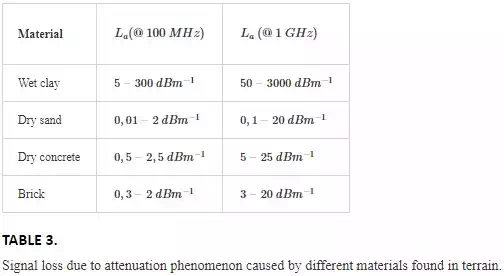
Table 3 summarises signal attenuation values depending on the terrain materials (that are typically encounter in Colombia) and signal frequency.
Besides modelling signal loss in Eq. (2), we have also considered the velocity of signal propagation (Vr) and the target penetration depth (d). With a soil-simplified model, considering a nonmagnetic isotropic and homogeneous medium both parameters can be computed as
![]()
![]()
where td is the signal’s delay time from the transmitting to the receiving antenna and c is the light velocity defined as c=3× 10⁸ ms−1c=3× 10⁸ ms−1. Relative dielectric permittivity(εr) is defined upon the medium where the electromagnetic wave is propagating. Therefore, there are two possible dielectric materials in the GPR scenario, the propagation in air and into the subsurface material. In the first place, the air relative permittivity is a well-known constant defined as εr = 1, and so the wave velocity can be rewritten as Vr = 30 cm/ns, with a wavelength between 300 and 30 cm (100 MHz–1 GHz). In the second place, the soil relative permittivity depends on the materials within the subsurface as, for example, if most of the subsurface materials are made of concrete with εr = 9, then the wave velocity can be computed as Vr = 10 cm/ns, with a wavelength between 100 and 10 cm (100 MHz–1 GHz). It is worth to notice that the velocity of propagation strictly depends on the relative permittivity, which means that the signal delay’s time can vary from medium to medium. This, of course, represents a challenge from the GPR resolution’s point of view.
In terms of depth resolution, some GPR applications measure depth by calculating the time involved between the signal reflection caused by the target and the receptor. However, this implies that the terrain has a clean subsurface (e.g. only ground besides the buried target). Clearly, landmine application demands to consider other types of buried elements. Those signals that are reflected by other elements that are not the target cause the clutter effect. The clutter can be defined as those chaotic signals that are measured at the same time and with similar spectral properties than the signal sample of interest. In order to identify the target among other elements (despite the clutter effect), the emitted signal must have a large bandwidth, and the antennas must have a high gain with significant aperture in the lower emitted frequencies. These features are called resolution plan.
In the model proposed both TX and RX antennas are placed with a common offset and depth point with respect to the target. Figure 6 shows this configuration. By properly setting the distance between the transmitter and the receiver, the received power (Pr) can be defined as
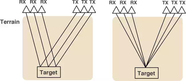
FIGURE 6.
(Left) Common offset; (right) common depth point.
![]()
Where α is the attenuation coefficient, θ is the angle of the middle point between both antennas and the vertical distance to the target, Pt is the power of the TX antenna and d is the distance to the target. Hence, the resolution plan is defined by half of the power measured in those points of signal dispersion (on the surface plane). The resolution can be estimated approximately as
![]()
Eq. (12) indicates that the resolution plan improves despite the attenuation increases, in which consequence enables the GPR system to process a constant signal despite the presence of noise and clutter.
HARDWARE
Figure 2 detailed the main components of the proposed GPR system by following an SDR architecture. This section presents a brief description of the hardware components used in the GPR system. The SDR technology has two main hardware components: (i) PC and (ii) A software radio peripheral.
Nowadays, the most representative companies that provide development SDR platforms are Ettus Research (with the Universal Software Radio Peripheral (USRP)), National Instruments (NI-Universal Software Radio Peripheral), Pentek, DataSoft (Thunder SDR), FlexRadio (SDR-1000), Realtek (rtl2832) and lately low-cost SDR platforms as FUNcube Dongle Pro for amateur radio applications. Among the different alternatives, Ettus Research has the largest market segment with a wide variety of SDR platforms with different performances; therefore, the SDR platform used for the GPR application was the USRP B210 from Ettus Research, where the baseband signal processing was performed by the PC on-board the UAV.
The USRP B210 board is divided into two internal boards (Figure 2(a)), the daughterboard which is in charge of the RF front-end functionalities of the radio system and the motherboard that handles all the digital signal processing, such as filtering, shifting and digital up-and-down conversion. Its main function is to deal with the signal’s quadrature (Q) and phase (I) components either of the transmitted (digital-to-analog conversion) or received signal (analog-to-digital conversion). As was the case with traditional RF transmitters/receivers (superheterodyne) where the baseband signal was transferred from baseband to an intermediate frequency (IF) and then from the intermediate frequency to the radio frequency, the USRP B210 (motherboard + daughterboard) is designed such that the digital up converter (DUC) performs the frequency transfer from baseband to IF band frequency and then the daughterboard will perform the IF band to RF band frequency transfer. On the other hand, the decimating filters or interpolators in the motherboard are used to reach the different binary rates that supports the serial connection (USB or Ethernet) required by the application. As for the clock signal to be used, it can be either external (SMA 1PPS, SMA Ext Ref, SMA GPS) or internal. The clock signal used between the FPGA, ADC, DAC and daughterboard converters was the internal one, in order to optimise the synchronisation of the device. Additionally, the daughterboard of the USRP B210 allows operating in half- or full-duplex mode with complex signals allowing a fully coherent 2 × 2 MIMO capability which is used for the pulse transmitting and receiving process in the GPR system
Thus, with the aforementioned information, the USRP B210 board has a frequency cover ranging from 70 MHz to 6 GHz; it is possible to modulate different signals (via SDR) depending on soil conditions. This makes the implemented system reconfigurable by the user at any time. The modulation process is handled by a FPGA spartan6 chip with a real-time bandwidth of 56 MHz. The antennas connected to the daughterboard of the USRP were designed by following the Vivaldi antipodal configuration, with a size of 10 × 8 cm and a bandwidth from 1.5 to 9 GHz with a gain of 7.3 dBi at 1.7 GHz and 4.3 dBi at 2.7 GHz.
The designed GPR is a time domain system where an impulse is applied to the antenna; there is a requirement for a linear-phase response, and this means that only a limited number of types of antenna can be used. The use of two separated antennas is due to the difficulty found with the use of a single antenna for transmission and reception, which would require an ultra-fast switch to operate in both channels, and since currently it is not possible to obtain commercially available switches to operate in the nanosecond region with sufficiently low levels of isolation between TX and RX ports, most surface-penetrating radar systems use separate antennas for transmission and reception in order to avoid interference from the transmitting antenna at the receiving antenna. Therefore, the cross-coupling level between the TX and RX antenna is a critical parameter in the antenna design for this kind of radars. Typically, a parallel dipole arrangement achieves a mean isolation of −50 dB, whereas for a directive antenna arrangement, such levels are higher depending on the antenna’s disposal and the directivity of the antenna itself.
On the other hand, the antenna’s performance is strictly linked with the terrain material, and in the case of the surface-penetrating radar sensing above the terrain, the antenna will radiate from the air into a half-space lossy material [5]. Some works in literature have reported antenna’s behaviour over lossy dielectric materials that summarise the cause modification of the antenna radiation pattern, both spatially and temporally, and should be taken into account in the system design. In addition, the propagation of electromagnetic pulses in a homogeneous conducting earth has been modelled in, and the dispersion of a rectangular pulse source suggests that the time domain characteristics of the received pulse could be used as an indication of distance.
In terms of frequency band, a typical antenna used in an impulse radar system would require to operate over a frequency range of a minimum octave and ideally at least a decade, 100 MHz–1 GHz. The input voltage driving function to the terminals of the antenna in an impulse radar is typically a Gaussian pulse, and this requires the impulse response of the antenna to be extremely short in order to not distort the input function generating time side lobes, which can illuminate clutter targets that are close to the target of interest degrading the radar resolution.
In order to have an antenna with a high bandwidth, the Vivaldi antenna was selected for the design. The Vivaldi antennas are part of the tapered slot antenna (TSA) family. This family belongs to the type of longitudinal-wave travelling antenna, i.e. plane antennas whose current and voltage distributions can be represented by one or more travelling waves, which usually travel in the same direction and propagate with a phase velocity less than or equal to the velocity of light. It provides an end-fire radiation and linear polarisation and can be designed to provide a constant gain-frequency performance. TSA are flat antennas that are built on a dielectric substrate. These vary according to the shape of the taper (i.e. the inner profile of the conductive material that goes over the dielectric). There are several kinds of profiles such as linearly tapered slot antenna (LTSA), constant-width tapered slot antenna (CWSA) and exponentially tapered slot antenna (ETSA). The Vivaldi antipodal antenna is characterised mainly by having a broader bandwidth with respect to the return losses of the antenna. Unlike the traditional Vivaldi antenna fed by a conventional microstrip line, the Vivaldi antipodal antenna separates the tapers by placing one on the front face of the dielectric and the other on the back face, as shown in Figure 7(a). In this structure, the feed is made by means of a microstrip line whose ground plane gradually narrows. The proper design of the transmission line ensures that this type of power is balanced and does not need the additional balun. The antipodal configuration guarantees having a wider bandwidth for the matching to the microstrip feed line. Additionally, recent works have shown that the introduction of slots in the antenna taper extends the bandwidth maintaining the good performance of the antenna in terms of radiation pattern and gain. Similarly, the use of slots in the taper has been shown to be an effective technique to significantly reduce the size of an antenna without affecting its performance, which is ideal for the on-board integration of the GPR with the UAV.
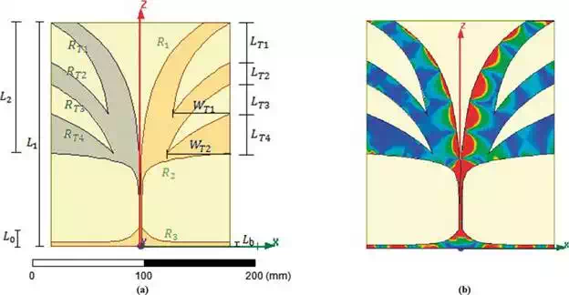
FIGURE 7.
(a) Vivaldi antipodal geometrical antenna parameters. (b) Electric current distribution.
Two Vivaldi miniaturised antipodal antennas for the pulse transmission and reception are integrated to the on-board GPR system, specially designed and fabricated for radar application. As was aforementioned, this configuration is ideal for GPR applications. Both RX/TX antennas are lightweight, with a symmetrical radiation pattern (curves slots), a bandwidth between 1.5 and 9 GHz, a substrate thickness and relative permittivity of 1 mm and 4.6, respectively. Figure 7(a) shows the geometrical parameters that directly affect the antenna bandwidth. The authors in performed several simulations in Ansoft HFSS aimed at determining the optimised values by means of a parametrical variation experiment. As a result, the geometrical parameters of the fabricated antennas are R1 = 25 mm, R2 =180 mm, R3 =120 mm, L0 = 17mm, L1 =204 mm, L2 =119 mm, = 3.4mm, RT1 =30 mm, RT2 = 20 mm, RT3=25 mm, RT4=25 mm, LT1=35.7 mm, LT2= 20.4 mm, LT3 =27.2 mm, LT4=35.7 mm, WT1=52.36 mm and WT2=57.12 mm. Figure 7(a) shows the electric field distribution on the plane of the antenna. The Tx and RX antenna’s radiation patterns are shown in Figure 8 for different frequencies in the working band showing good agreement between measured and simulated data. Further details regarding the antennas design, simulation and fabrication are found in.
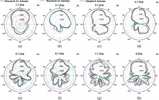
FIGURE 8.
Measured and simulated radiation patterns of TX and RX antennas for the on-board GPR system in different bands: (a) 1.7 GHz, (b) 2.7 GHz, (c) 3.7 GHz, (d) 4.7 GHz, (e) 5.7 GHz, (f) 6.7 GHz, (g) 7.7 GHz, (h) 9 GHz.
SOFTWARE
The driver needed to work with the USRP B210 is the USRP Hardware Driver (UHD); it is a library written in C ++ designed to work on Linux, Windows and Mac OS. The main purpose of the driver is to provide control over Ettus products; the use of this software can be used stand-alone or by using other applications such as GNU Radio, LabVIEW, Simulink and OpenBTS. The software implementation of the GPR system can be done under GNU Radio software because it is open and free source and provides a friendly signal processing block interface. Additionally, it is a simulation tool that can be used together with RF hardware (USRP) to physically implement radio software systems.
The GNU Radio project was started in 2001 and was founded by Eric Blossom with the aim of developing a framework for radio software. It consists of a set of files and libraries that provide signal processing blocks, allowing the design and simulation of systems based on radio software. This software tool can be used with additional external hardware such as the USRP, providing the possibility of physically implementing a system based on radio software. The operation of GNU radio can be conceived as a graph, where nodes symbolise signal processing blocks, and the interconnection between them will determine the path that the signal will follow starting from a source and terminating in a sink. Further details of GNU Radio software features, functionalities and applications can be found in its website.
GNU Radio applications can typically be programmed in two ways: (i) directly on Python or (ii) using the GNU Radio Companion graphical tool. The second option arises as a need to facilitate the task to the user as much as possible, thus minimising the application programming. The Tx and Rx GPR systems are programmed by using the GNU Radio Companion option, described as follows.
The GPR Tx system consists basically in the generation of the transmission impulse. Even though the theory dictates that the signal generated for impulse-based radar must be infinite band, in practical this is not possible because of the technology restrictions of the GPR system’s elements. In this case, the generated pulse is band limited since the USRP B210 card has a bandwidth approximately of 56 MHz. Therefore, the proposed objective for the designed impulse-based GPR system is to generate a signal with that spectral technology restriction.
The classic rectangular impulse does not cause inter-symbol interference (ISI); however, an infinite bandwidth and significant transmission power are required. For a wireless communication channel, it is necessary to meet the Nyquist ISI criterion, the ISI is generated when consecutive signals are sent through the communication channel and the replicas of the previously sent signals generate interference to the signals that are currently going through the channel which makes the system less robust against noise. To minimise the ISI in a communication channel and concentrate the power within the desired bandwidth, the pulse shaping technique is used to shape the impulse according to a specific digital filter; as a consequence, the effective bandwidth and power are concentrated on the main harmonic of the transmitted signal. Not all filters can be used as a shaping filter since some of them can actually increase the ISI, so the selection must meet the Nyquist criterion. To this purpose the most common filters are the sinc filter, raised-cosine (RC) filter and the Gaussian filter. Besides, it is important in the reception to include a matched filter according to the transmission filter used. According to this a RC filter was selected because the sync filter is not physically realisable since it is a non-causal filter, and the Gaussian filter is also not viable because it does not have zero crossings and is typically used to generate frequency shifts.
The mathematical function of a RC filter is defined as follows:

where Ts is the sampling time, β is the roll-off factor which is used to determine the impulse spectrum bandwidth given by Eq. (14):
![]()
where Rs is the symbol rate. According to the inverse transform of Z(f) of the filter, z (t) = 0 for t = ∓T_s, ∓2T_st = ∓T_s, ∓2T_s; therefore, for a RC filter, zero crossings are functions of the roll-off factor.
In order to build a RC impulse in GNU Radio companion, first it is necessary to define a square signal and then filter it. However, GNU Radio does not have a square impulse signal generator block; therefore, a well-known method is used, which consists in the multiplication of four square signals with a useful cycle of the 50%, each of them with different frequencies following the rule (f, 2f, 4f). With this method it is possible to generate a rectangular pulse train of frequency f and a pulse width 1/4f where the pulse width can be made as small as desired, but there are bandwidth limitations. Thus, to generate the transmission signal, the signal source block is used with the square waveform option selected, as is shown in Figure 9.
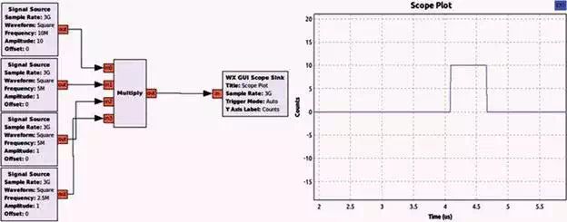
FIGURE 9.
Rectangular pulse train generator in GNU Radio Companion.
With the generated square pulse, it is now necessary to give the form of a RC pulse passing through an elevated cosine root filter which in GNU Radio is known as root-raised-cosine filter block. The description of this block is described in Figure 10.
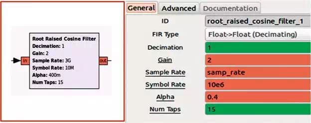
FIGURE 10.
GNU Radio RC filter block parameters.
Within the RC Filter block, it is possible to set the decimation value, filter gain, sampling rate, symbol rate, roll-off factor (alpha) and number of taps for floating and real values according to the criteria of design and operation of the filter. The choice of decimating or interpolating is very important in the filter design, and the two are the equivalent of a down-sampling and up-sampling process, respectively. Both are integer values that allow increasing or decreasing the number of times a sample is replicated in the ADC process. The symbol rate (baud rate or modulation rate) is the number of pulses per unit of time (pulse/second).
The RC filter is a finite impulse response (FIR) filter used for pulse shaping which means that its impulse response has a finite duration. This parameter is set by the number of taps, which for this application is 15 by default.
After the generation of the RC pulse, an additional modulation process is considered for further distortion reduction. The final transmission pulse is shown in Figure 11.
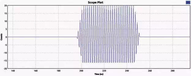
FIGURE 11.
RC transmission pulse.
The received signal (Rx) is processed in order to detect a buried landmine. To this purpose, we need to introduce the following procedures: (i) signal filtering, (ii) setting a gain for quantifying the incoming power and (iii) designing the detection algorithm. By using the USRP source block provided by GNU Radio, we can set up the gain, the central frequency and the sample rate.
On the other hand, as was mentioned before, the detection algorithm is based on a matched filter that enables to maximise the signal factor despite the noise (high signal-to-noise ratio (SNR)); in other words, it enables to detect the waveform of the signal (emitted pulse) despite the noise. The matched filter is a linear filter normally used in radar systems designed to detect a pulse shapes despite the presence of clutter noise. Once the drone has covered an entire terrain, the data captured by the GPR is post-processed in order to generate a heat map. Hence, Rx signal is of the form
![]()
where (t) is the transmitted pulse, t0 is an unknown delay and A is a scaling factor. The output of the filter is υ(t)=υ(t)*h(t)=y(t)+n0(t)υ(t)=υ(t)*h(t)=y(t)+n0(t), where h(t) is the impulse time response after applying the convolution property (A+B)*C=A*C+B*C(A+B)*C=A*C+B*C. Hence
![]()
![]()
In time, the term td in Eqs. (18) and (19) represents the time when the transmitted pulse is received by the Rx antenna. The expression for the SNR can be written as
![]()

By applying the inequality Cauchy-Schwartz in Eq. (19), the response of the filter is
![]()
By assuming white noise, Sn (ω) is the constant, and considering the Fourier transformation properties described in Eqs. (21) and (22), the expression for the filter response can be written as in Eq. (23):
![]()
![]()
![]()
Based on the above considerations, the filter used as a matched filter is also a RC filter.
In the post-processing stage, the way of indicating a mine presence to the user has two approaches: by audio and by construction of a heat map. The audio recognition method is similar in operation to that of a conventional metal detector which emits an audible signal under the event of a positive mine detection. When a target is located, the received power is greater, and consequently the response’s amplitude of the matched filter is also greater; then the signal is processed by a function in GNU Radio to obtain the RMS value of the signal and is sent to a VCO where it fits the audible spectrum so that the sound is differentiable with respect of a non-mine event. The blocks in GNU Radio that describe this function are shown in Figure 12.

FIGURE 12.
Audio mine indicator system in GNU Radio Companion.
On the other hand, the method of recognition by construction of a heat map unlike the acoustic method requires further processing of the results. To this purpose, the GPR data are exported with a file sinkblock from GNU Radio for post-processing in MATLAB. Results are shown in Section 4.
SDR-based GPR integration on-board UAV
This section describes the on-board integration process between the GPR system and the UAV. The process includes the integration of hardware, software and the mechanical parts corresponding to the necessary supports for the correct coupling of both systems for a suitable flight plan for the GPR correct function. Being independent devices, the UAV and the GPR need a mechanical supports specially designed to fit with the physical area of the UAV system. In addition, it is also necessary to establish continuous communication between the equipment in such a way that the flight system is in charge of assigning processes, while the GPR system is a peripheral that executes those processes. Finally, the data obtained by the GPR together with the GPS data and positioner values of the board must be correctly archived, so that the base station can extract and post-process them for further analysis.
MECHANICS
The mechanical integration of the radar with the UAV is realised by means of an adjustable, resistant and light support, which allows several antenna positions according to the height of flight and the depth distance of the buried landmines. For the support design, the geometric model (Figure 4) is taken into account for the signal transmission and reception. As was mentioned in Section 2.2, the designed GPR system is implemented using the Ettus USRP B210 card from Ettus Research and two antipodal Vivaldi antennas especially designed for radar applications explained in Section 2.2.2. Based on the above, the CAD models were designed for each of the necessary components.
For the SDR support CAD model, the physical dimensions of the SDR card were taken into account and designed in such a way that the card would slide through the support and be adjusted with the SMA connectors at one end. The model is shown in Figure 13.
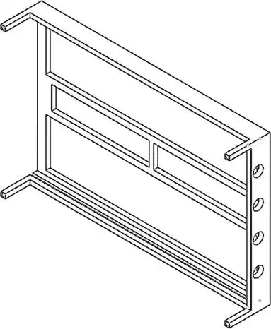
FIGURE 13.
SDR support CAD model: large 15.77 mm, width 103 mm and height 28 mm.
For supporting the antennas and SMA cables, an adjustable rail system is designed in such a way that the separation between the antennas is variable between a minimum distance of 307.66 mm and a maximum distance of 669.69 mm. The separation distances were computed from the geometrical model considering that the inclination angle of the TX and RX antennas can vary from 8° to 18° and the relative terrain permittivity between 4 and 8, approximately. The different configurations allow setting the best receiving signal scenario depending of the landmine depth. One of the arms of the adjustable rail system is shown in Figure 14. The complete CAD model of the adjustable rail system is shown in Figure 15.
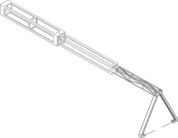
FIGURE 14.
Arm of the adjustable rail system CAD model with the antenna support.
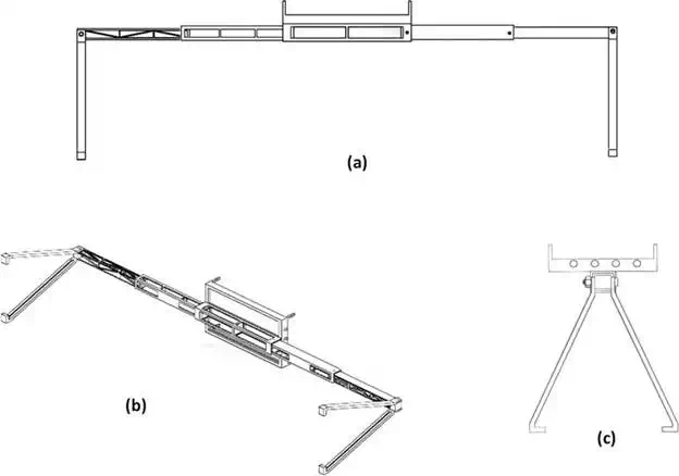
FIGURE 15.
Rail system CAD model: (a) front view, (b) isometric view and (c) lateral view.
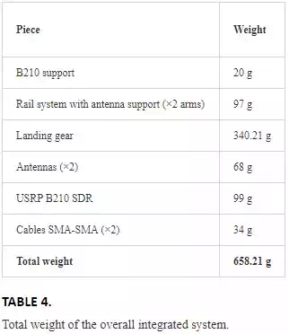
The designed CAD models are fabricated using the 3D object professional printer using a simulated polypropylene material that gives strength and flexibility to the structure. The weight for the total and each piece of the mechanical support are given in Table 4. It is worth to notice that the total weight meets the restriction of the UAV payload.
COMMUNICATIONS
The UAV has by default a 64-bit Linux operating system. However, due to compatibility problems, GNU Radio is installed over a bootable USB memory with a 64-bit Ubuntu 14.04 operating system. In this fashion, the UAV Mastermind instead of starting with the default operating system started with Ubuntu from the USB allowing the operation of the GPR system.
On the other hand, the communication between the computer on-board and the base station is made by means of the SSH protocol since it has strong security protocols and it ensures a stable process execution by keeping processes running on the server until the link is re-established when communication with the client is lost.
GRAPHICAL USER INTERFACE (GUI)
The GUI enables the user to set up the desired trajectory (waypoint navigation) (Figure 19(a)), key parameters of the GPR and other features such as saving a log file of the flight or computing a terrain image mosaic with the sequences of images captured by the drone during flight. This work has been approached in a previous work cited in.
LANDMINE DETECTION AND GEO-MAPPING
The Autopilot card of the UAV is programmed using the so-called variable wpreached that allows knowing if the UAV is inside a waypoint. The UAV is programmed using the Eclipse software and the help of the AscTec wiki which contains the entire development package and corresponding codes for the programming of the Autopilot card. The programming of wpreached is done in an SDK.c file. Within this file there is an example of waypoint tracking, in which the UAV performs a square of 15 × 15 m. Therefore, a new wpreached subroutine was created to guide automatically the UAV through waypoints, including the execution commands of the GPR. The GPR data acquisition is done for each of the defined trajectories by the Autopilot program with the settled waypoints as shown in Figure 16.
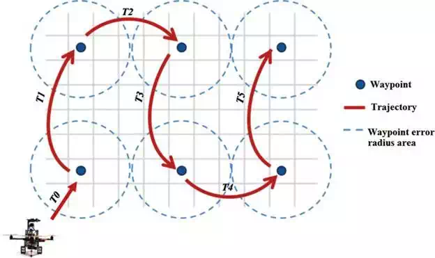
FIGURE 16.
Autopilot trajectory UAV workplan with waypoints.
The data are stored in two self-contained folders in the mastermind’s desktop, one with the GPS and one with GPR data. The results of the GPR are stored automatically in GNU Radio in a binary file with different names for each of the trajectories. On the other hand, the GPS and IMU data are stored in a text file which is divided into six columns representing the data of each required value. The renaming and creation of radar and GPS files, respectively, are done autonomously without user intervention during the rest of the time of the UAV at the waypoints.
In order to geo-locate the identified landmine targets within an image (geodesical position), the odometry between consecutive images has been computed by using the on-board IMU data of the UAV. Once the landmine is geo-located, a map of the terrain is created by computing an image mosaic. Image mosaicking is a process for building a panoramic image that result from combining multiple photographic images taken with an on-board camera. The geodesic coordinates of the detected landmines are obtained by using the UAV on-board GPS through a robot operating system (ROS) package called drone_GPS which enables to transform geodesic coordinates captured by the GPS into Universal Transverse Mercator (UTM) coordinates for positing the robot on earth. Further details of landmine geo-mapping can be found in.
Results
Recalling the workflow depicted in Figure 17, the steps followed in order to perform a mission are as follows: (i) the operator selects the GPS coordinates of the starting point of the mission (via Google Earth). By using the GUI of the ground station, the operator defines the path to cover a desired area. (ii) Before proceeding to real experiments, the operator must start the simulator (requires MATLAB) in order to verify that the drone is able to operate at the desired altitude and speed. (iii) Once the mission is validated, the operator must send the mission parameters to the drone (via clicking send in the GUI), including list of trajectory waypoints, commanding height and speed and GPR configuration parameters. (iv) By clicking start, the drone waits until the operator takes off manually up to about 1 mover the ground. Using the RC controller, the operator switches to autonomous mode. The drone’s altitude control positions the drone at about 50 cm aimed at ensuring proper GPR performance. The autopilot position control uses GPS feedback to track the path waypoints, while a backstepping+DAF attitude control enables steady flight [42]. The operator is able to abort the mission by moving any stick of the RC controller. (v) Once the drone finishes the mission, the drone sends all data to the base station and waits for manual landing. (vi) Within the base station, the operator can visualise GPR results and the geo-mapped terrain. The forthcoming section presents the experimental results for the integrated aerial system for landmine detection.
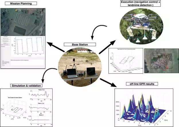
FIGURE 17.
Operation workflow of the UAV with an on-board GPR integrated system.
LANDMINE DETECTION RESULTS
Experiments with the complete system have been carried out nearby a small rural area. The drone covered a small terrain with an area of 35 m2, with a flying speed of 0.12ms−1 and a mission time of 100s. In the experiment setup, there are three buried landmine prototypes along the terrain: (#1) bottle-made artefact, (#2) fully metallic artefact and (#3) PBC tube-made artefact. The insets of Figure 18(a)depict each prototype. Artefact (#1) is a bottle buried at 20 cm in depth with 8 cm of diameter and 20 cmin length with 20% of non-uniform metal component. It covers an area of 16 m2. In some countries like in Colombia, most of the landmines are hand-crafted; this is why the enclosures are typically made by such components. In the inside of the bottle lies the explosive, copper cables, battery and tape. Artefact (#2) is a fully metallic buried at 10 cm in depth with 25 cm of diameter and 10 cm in length, and it covers an area of 156 cm2. Artifact (#3) is a PBC tube buried at 20 cm in depth with 16 cm of diameter and 10 cm in length, and it covers an area of 60 cm2. In the inside, artefact (#3) has 30% of non-uniform metal component.
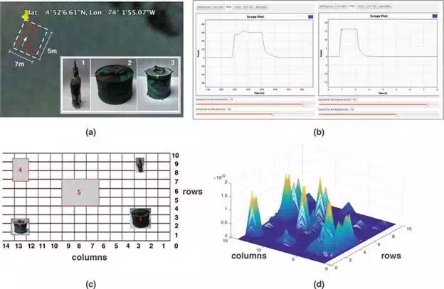
FIGURE 18.
Experimental landmine detection results: (a) the corresponding field for testing the system. The insets show three landmine artefacts of different forms, sizes and materials; (b) signal processed by the GPR using SDR GNU radio: in the left, a signal with large amplitude indicating a buried artefact; (c) grid showing the location of each element, including the three landmine artefacts and two additional non-landmine elements; (d) heat map computed from the GPR/GPS data after the experiment. Large peaks correspond to a detected object.
In addition, other two types of metallic elements are buried working as false alarms. Figure 18(c)shows how these five elements (three landmines and two false landmines) are spatially distributed along the terrain. Elements #4 and #5 are fully metallic layers with 15 × 15 × 15 cm and 20 × 15 ×5 cm, respectively, both buried at 15 cm in depth and covering an area of 225 cm2 and 300 cm2. We divided the entire area within cells in order to map the position of the artefacts detected by our system. Internally, the GPR detection signal looks like the ones depicted in Figure 18(b): in the left, we have a signal with larger amplitude compared to the right one, meaning that a possible landmine has been detected. Finally, Figure 18(d) shows the generated heat map with the GPR results. This map condenses the results of 20 different instance measurements carried out over the same surface described in Figure 18(c).
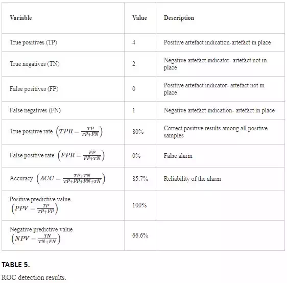
Experiments were conducted with an average ambient temperature of 14°C with an average solar radiation of 4.4kW/m2 and a relative humidity of 72%. This means that the soil was always a little bit wet, which consequently makes difficult full penetration of the GPR signal below the surface. To quantify the performance of our system in terms of accuracy and reliability, we have calculated the receiver operating characteristic (ROC) data detailed in Table 5.
Comparing the results from the heat map in Figure 18(d) against the location of the artefacts from Figure 18(c), note that the landmine (#1) (bottle-made artefact) was not properly detected. The corresponding GPR signal for landmine (#1) can be barely observed in the coordinates: rows 8–9 with column 3. As mentioned, the enclosure of this artefact was entirely made of plastic with only 20% of non-uniform metal component in the inside. Other critical issues rely on the small transversal area of the artefact, about 16 cm2. Recalling the geometrical model defined in Figure 4, the angle θ2 enables to set up the GPR aimed at detecting buried artefacts of larger size and length but with small transversal area, such as the bottle. However, there is a limit in the amount of area and the amount of metal in the material.
It was experimentally found that the limit with the measurements carried out for the artefact (#3): a tube-made artifact with an enclosure made of PBC with 30% of non-uniform metal component in the inside. Comparing Artefact (#3) with (#1), both are buried at the same depth with similar morphology, but the former has a larger diameter; thus, it has a larger area of 64 cm2. Also, the former has 10% more metal in the inside. The corresponding GPR signal for landmine (#3) was fully detected in the coordinates: rows 1–2 with column 13.
The corresponding GPR signal for landmine (#2) was fully detected in the coordinates: rows 1–5 with columns 2–4. This artefact was fully made of metal with a transversal area of 156 cm2. Finally, elements (#4) and (#5) (metallic layers acting as false landmines) were also detected by our system. In real missions for demining (mine detection and clearence), buried metallic objects that do not correspond to real landmines will be detected as landmines (true negatives). In summary, the designed system under the aforementioned operational characteristics will have an accuracy of 85%, a true positive rate of 80%, a positive predictive value of 100% and a negative predictive value of 66.6%.
GEO-MAPPING RESULTS
In this subsection, experimental results of the geo-mapping process are presented. In overall, it has been analysed 28,029 images captured by the drone during flight. On average, the drone has covered terrain areas ranging from 15 m2 to 80 m2 with a flight altitude ranging from 0.5 m to 1.5 m. Figure 19(a)shows the trajectory followed by the drone while covering an area of 80 m2. The red circles represent the GPS coordinates of the detected landmine objects during flight.
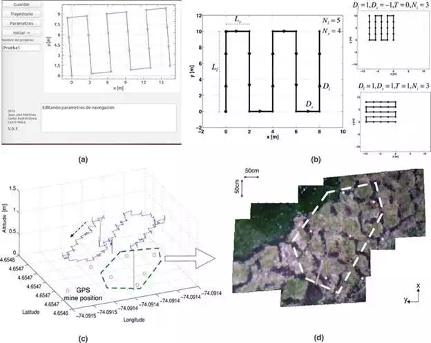
FIGURE 19.
(a) Initial GUI for the setting of the waypoint of the flight plan. (b) Trajectory plan generation and navigation control. (c) Experimental 3D trajectory of the UAV: covered area of 80 m2 at 2560 mabove the sea level. The red circles are GPS coordinates of the detected landmine objects. The inset shows how the detected target is displayed to the user via the base station’s interface, (d) panoramic image of the covered terrain. The mosaic map was created by applying a stitching method to the images captured by the quadrotor during flight.
Conclusions
This chapter has presented the development of a custom-designed lightweight GPR by approaching interplay between hardware and software radio. Additionally, the chapter introduces the integration of the aforementioned SDR-based GPR into an autonomous aerial drone (UAV). The performance of the GPR from the results obtained validates the possibility to integrate a lightweight radar system into a UAV.
In terms of GPR performance, the directional antennas radiated and received more power in a specific direction, which consequently increased the detection by means of reducing the interference caused by other sources. Also, thanks to the mathematical model derived for the GPR system, we were able to design a SDR-based GPR that can be reconfigured during operation. This introduces the possibility of adjusting the GPR (power, frequency, bandwidth, carrier, etc.) depending on the testing scenario. In overall, our proposed system was able to detect buried artefacts with smaller transversal areas that do not necessarily need to be made full of metal. The outdoor experiments have enabled us to establish the following conditions and limit for an accurate detection: relative humidity > 70% (semi-wet or dry terrain), artefact depth 20 cm, and diameter (> 15 cm) with a transversal area > 16 cm2 and > 30% of the material made of metal.
