Optical Shaft Encoders
The servomechanism described in the previous section is based on analogue feedback technology, using a potentiometer and a tachometer generator. These analogue feedbacks, although simple, are no longer used in industrial robots and other industrial applications, due to limited reliability and performance. A potentiometer, for example, is poor in reliability, resolution, accuracy, and signal to noise ratio. The output tap of the variable resistance slides on a track of resistive material, making a mechanical contact all the time. This slide contact causes not only electric noise but also wear of the contacting surfaces. The resolution and S/N ratio of the sensor are also limited by the mechanical contact. Furthermore, linearity depends on the uniformity of the resistive material coated on the substrate, and that is a limiting factor of a potentiometer’s accuracy. Today’s industrial standard is optical shaft encoders, having no sliding contact. This will be discussed next.
Basic principle
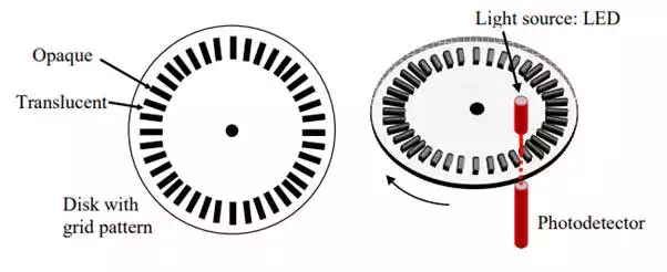
An optical encoder consists of a rotating disk with grids, light sources, photodetectors, and electronic circuits. As shown in Figure 2.5.1, a pattern of alternating opaque and translucent grids is printed on the rotating disk. A pair of light source and photodetector is placed on both sides of the rotating disk. As an opaque grid comes in, the light beam is blocked, while it is transmitted through the disk, when the translucent part comes in. The light beam is then detected by the photodetector. The disk is coupled to a motor shaft or a robot joint to measure. As it rotates, an alternating ON-OFF signal is obtained with the photodetector. The number of grids passing through the optical elements represents the distance traveled.
Basic construction of optical shaft encoder
This optical shaft encoder has no mechanical component making a slide contact, and has no component wear. An optical circuit is not disturbed by electric noise, and the photodetector output is a digital signal, which is more stable than an analogue signal. These make an optical shaft encoder reliable and robust; it is a suitable choice as a feedback sensor for servomotors.
Position measurement
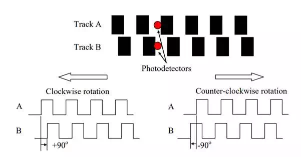
One problem with the above optical encoder design is that the direction of rotation cannot be distinguished from the single photodetector output. The photodetector output is the same for both clockwise and counter-clockwise rotations. There is no indication as to which way the disk is rotating. Counting the pulse number merely gives the total distance the shaft has rotated back and forth. To measure the angular “position”, the direction of rotation must be distinguished. One way of obtaining the directional information is to add another pair of light source/photodetector and a second track of opaque/translucent grids with 90 degrees of phase difference from the first track. Figure 2.5.2 illustrates a double track pattern and resultant output signals for clockwise and counter-clockwise rotations. Note that track A leads track B by 90 degrees for clockwise rotation and that track B leads track A for counter-clockwise rotation. By detecting the phase angle the direction of rotation can be distinguished, and this can be done easily with an up-down counter.
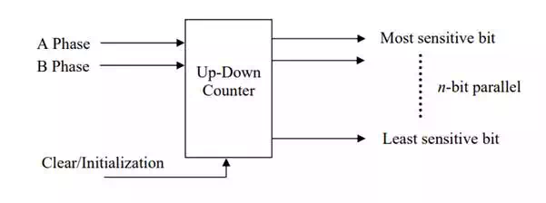
By simply feeding both A phase and B phase encoder signals to an up-down counter, the direction of rotation is first detected, and the number of rising edges and falling edges of both signals is counted in such a way that the counter adds the incoming edge number for clockwise rotation and subtract the edge numbers for counter-clockwise rotation. The up-down counter indicates the cumulative number of edges, that is, the angular “position” of the motor. The output of the up-down counter is binary n-bit signals ready to be sent to a digital controller without A/D conversion.
Double track encode for detection of the direction of rotation
It should be noted that this type of encoder requires initialization of the counter prior to actual measurement. Usually a robot is brought to a home position and the up-down counters are set to the initial state corresponding to the home position. This type of encoder is referred to as an incremental encoder, since A-phase and B-phase signals provide relative displacements from an initial point. Whenever the power supply is shut down, the initialization must be performed for incremental encoders.
Up-down counter for an incremental encoder
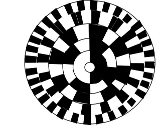
An absolute encoder provides an n-bit absolute position as well as the direction of rotation without use of an up-down counter and initialization. As shown in Figure 2.5.4, the rotating disk has n-tracks of opaque-translucent grid patterns and n pairs of light sources and photodetectors. The n-tracks of grid patterns differ in the number of grids; the innermost track has only 1=20 pair of opaque and translucent slits, the second track has 2=21 pairs, and the i-th track has 2i-1 pairs. The n outputs from the photodetectors directly indicate the n-bit absolute position of the rotating disk. In general, absolute encoders are more complex and expensive than incremental encoders. In case of power failure, incremental encoders need a laborious initialization procedure for recovery. For quick recovery as well as for safety, absolute encoders are often needed in industrial applications.
Absolute encoder
Velocity estimate
Velocity feedback is needed for improving accuracy of speed control as well as for compensating for system dynamics. A salient feature of optical encoders is that velocity information can be obtained along with position measurement. Without use of a dedicated tachometer generator, velocity measurement can be attained by simply processing pulse sequences generated by an optical encoder.
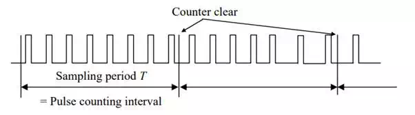
a pulse sequence coming from an optical encoder.2 Each pulse indicates a rising edge or a falling edge of phase A & B signals. Therefore, the density of this pulse train, i.e. the pulse frequency, is approximately proportional to the angular velocity of the rotating shaft. The pulse density can be measured by counting the number of incoming pulses in every fixed period, say T=10 ms, as shown in the figure. This can be done with another up-down counter that counts A phase and B phase pulses. Counting continues only for the fixed sampling period T, and the result is sent to a controller at the end of every sampling period. Then the counter is cleared to re-start counting for the next period.
As the sampling period gets shorter, the velocity measurement is updated more frequently, and the delay of velocity feedback gets shorter. However, if the sampling period is too short, discretization error becomes prominent. The problem is more critical when the angular velocity is very small. Not many pulses are generated, and just a few pulses can be counted for a very short period. As the sampling period gets longer, the discretization error becomes smaller, but the time delay may cause instability of the control system.
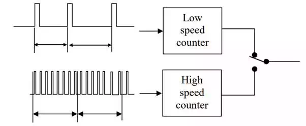
Velocity estimate based on pulse frequency measurement
An effective method for resolving these conflicting requirements is to use a dual mode velocity measurement. Instead of counting the number of pulses, the interval of adjacent pulses is measured at low speed. The reciprocal to the pulse interval gives the angular velocity. As shown in Figure 2.5.6, the time interval can be measured by counting clock pulses. The resolution of this pulse interval measurement is much higher than that of encoder pulse counting in a lower speed range. In contrast, the resolution gets worse at high speed, since the adjacent pulse interval becomes small. Therefore, these two methods supplement to each other. The dual mode velocity measurement uses both counters and switches them depending on the speed.
Dual mode velocity measurement