PWM switching characteristics
As the PWM frequency increases, the current driven to the motor becomes smoother, and the nonlinearity due to discrete switching disappears. Furthermore, high PWM frequencies cause no audible noise of switching. The noise disappears as the switching frequency becomes higher than the human audible range, say 15 kHz. Therefore, a higher PWM frequency is in general desirable. However, it causes a few adverse effects. As the PWM frequency increases:
• The heat loss increases and the transistor may over-heat,
• Harmful large voltage spikes and noise are generated, and
• Radio frequency interference and electromagnetic interference become prominent.
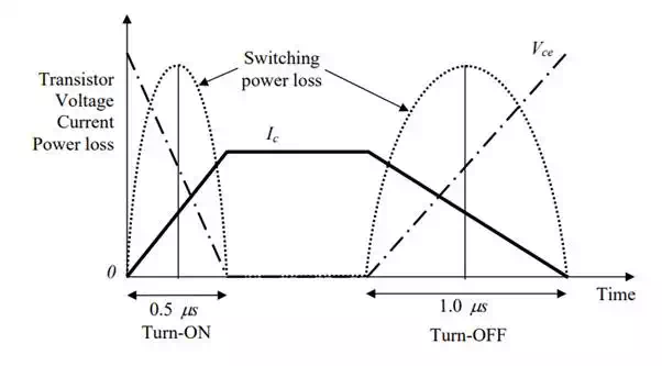
The first adverse effect is the most critical one, which limits the capacity of a PWM amplifier. Although no power loss occurs at the switching transistor when it is completely ON or OFF, a significant amount of loss is caused during transition. As the transistor state is switched from OFF to ON or vice versa, the transistor goes through intermediate states, which entail heat loss. Since it takes some finite time for a semiconductor to make a transition, every time it is switched, a certain amount of power is dissipated. As the PWM frequency increases, more power loss and, more importantly, more heat generation occur. Figure 2.3.5 illustrates the turn-on and turn-off transitions of a switching transistor. When turned on, the collector current Ic increases and the voltage Vce decreases. The product of these two values provides the switching power loss as shown by broken lines in the figure. Note that turn-off takes a longer time, hence it causes more heat loss.
Transient responses of transistor current and voltage and associated power loss during turn-on and turn-off state transitions
it is clear that a switching transistor having fast turn-on and turn-off characteristics is desirable, since it causes less power loss and heat generation. Power MOSFETs (Metal-Oxide-Semiconductor Field-Effect Transistors) have very fast switching characteristics, enabling 15 ~ 100 kHz of switching frequencies. For relatively small motors, MOSFETs are widely used in industry due to their fast switching characteristics. For larger motors, IGBTs (Insulated Gate Bipolar Transistor) are the rational choice because of their larger capacity and relatively fast response.
As the switching speed increases, the heat loss becomes smaller. However, fast switching causes other problems. Consider eq.(2.1.4) again, the dynamic equation of the armature:
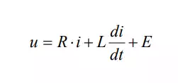
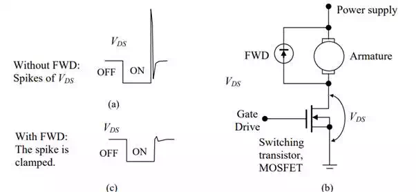
High speed switching means that the time derivative of current i is large. This generates a large inductance-induced kickback voltage dt di L that often damages switching semiconductors. As illustrated. a large spike is induced when turning on the semiconductor. To get rid of this problem a free-wheeling-diode (FWD) is inserted across the motor armature, as shown in Figure 2.3.6-(b). As the voltage across the armature exceeds a threshold level, FWD kicks in to bypass the current so that the voltage may be clamped.
Voltage spike induced by inductance (a), free-wheeling diode (b), and the clamped spike with FWD (c)
High speed PWM switching also generates Electromagnetic Interference (EMI), particularly when the wires between the PWM amplifier and the motor get longer. Furthermore, high speed PWM switching may incur Radio-Frequency Interference (RFI). Since the PWM waveforms are square, significant RFI can be generated. Whenever PWM switching edges are faster than 10 µs, RFI is induced to some extent. An effective method for reducing EMI and RFI is to put the PWM amplifier inside the motor body. This motor architecture, called Integrated Motor or Smart Motor, allows confining EMI and RFI within the motor body by minimizing the wire length between the motor armature and the power transistors.
The H-bridge and bipolar PWM amplifiers
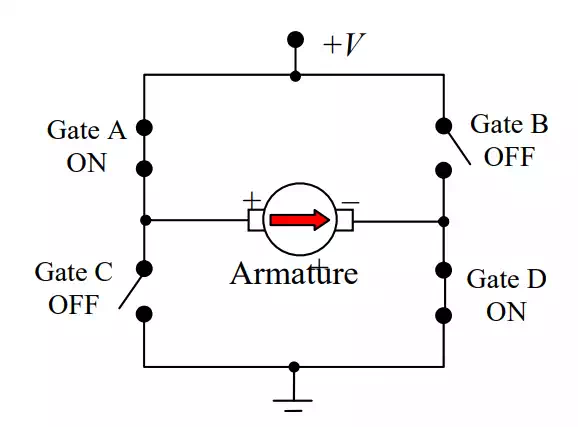
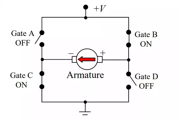
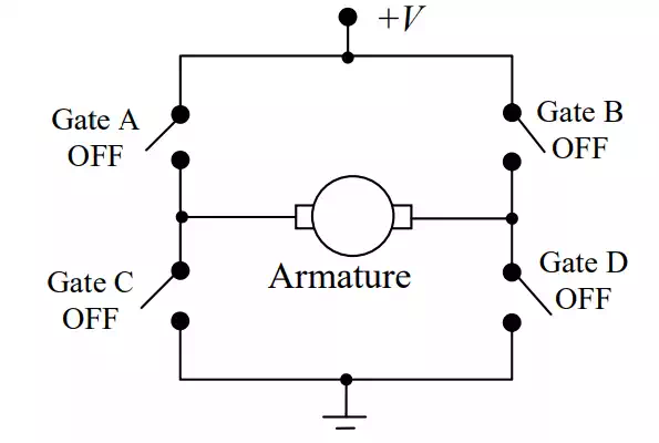
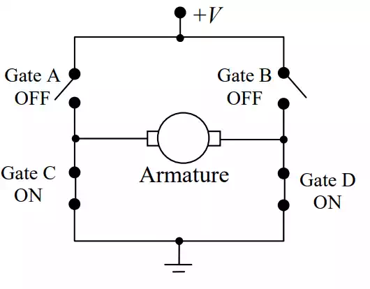
In most robotics applications, bi-directional control of motor speed is necessary. This requires a PWM amplifier to be bipolar, allowing for both forward and backward rotations. The architecture described in the previous section needs to be extended to meet this bipolar requirement. The H-Bridge architecture is commonly used for bipolar PWM amplifiers. As shown in Figure 2.3.7, the H-Bridge architecture resembles the letter H in the arrangement of switching transistors around the motor armature. Switching transistors, A and B are pulled up to the supply voltage V, whereas transistors C and D are connected to ground. Combinations of these four switching transistors provide a variety of operations. In figure (i), gates A and D are ON, and B and C are OFF. This gate combination delivers a current to the armature in the forward direction. When the gate states are reversed, as shown in figure (ii), the direction of current is reversed. Furthermore, the motor coasts off when all the gates are turned OFF, since the armature is totally isolated or disconnected as shown in figure (iii). On the other hand, the armature windings are shortened, when both gates C and D are turned ON and A and B are turned OFF. See figure (iv). This shortened circuit provides a “braking” effect, when the motor rotor is rotating.
Forward motion
Reverse motion
The motor armature coasts off
The motor windings are shortened causing a braking effect.
It should be noted that there is a fundamental danger in the H-bridge circuit. A direct short circuit can occur if the top and bottom switches connected to the same armature terminal are turned on at the same time. A catastrophic failure results when one of the switching transistors on the same vertical line in Figure 2.3.7 fails to turn off before the other turns on. Most of H-bridge power stages commercially available have several protection mechanisms to prevent the direct short circuit.
Robot Controls and PWM Amplifiers of the 2.12 Laboratory
DC motors and PWM amplifiers, the two most important components involved in a robot power train, have been described. Now we are ready to introduce the specific drive system and controls to be used for building robots for the design project.
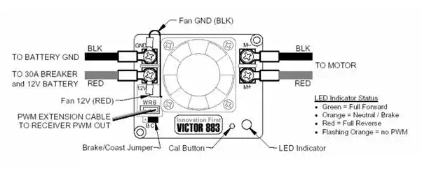
This term we will use controllers and drives produced by Innovation First, Inc. The system consists of bipolar PWM amplifiers, a PIC-based on-board robot controller with a wireless modem, a stationary controller hooked up to a laptop computer. Potentiometers are used for measuring the angular displacement of joint axes. They are connected to A/D converter ports of the on-board controller for position feedback control. Additional sensors can be hooked up to the on-board controllers. A C-language based development environment is available for the system.
Bipolar PWM amplifier with a built-in cooling fun, IFI, Inc.
On-board and stationary controllers, IFI.Inc
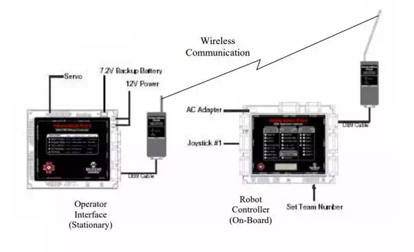
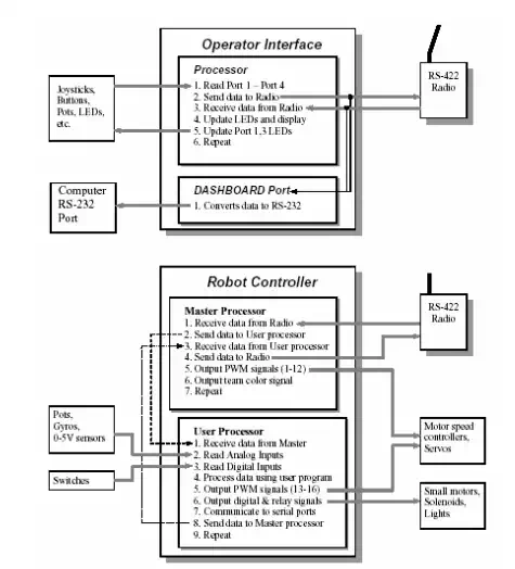
Control system operation diagram, IFI, Inc.